

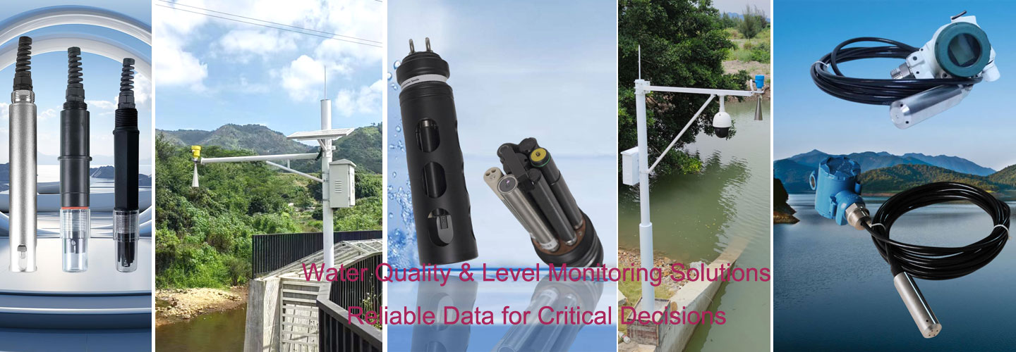
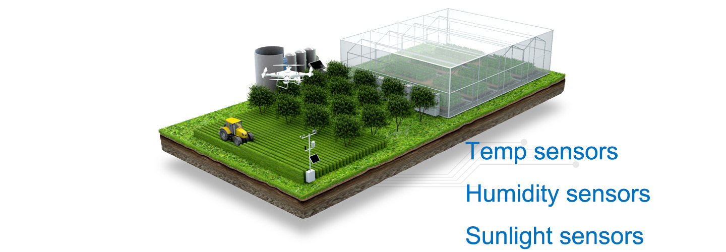

Dust monitoring at a fixed outdoor station measures airborne particulate concentration through an inlet, sampling airflow, optical detector and logger. The sampling path must deliver representative air without trapping particles or drawing cabinet exhaust. Choose a protected, unobstructed inlet first; adding tubing to an integrated fan sensor requires separate engineering approval.
Follow the air through a fixed dust monitoring station
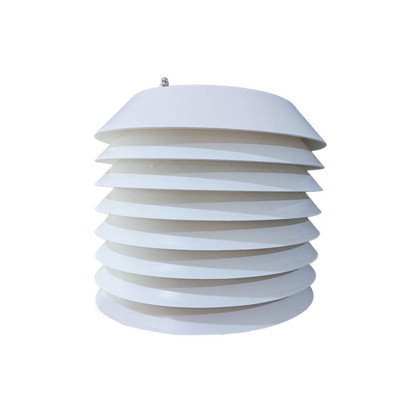
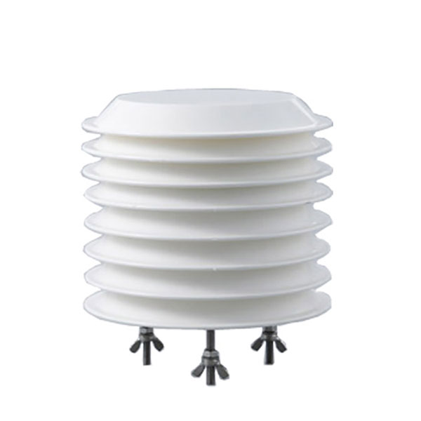
PM2.5/PM10 Integrated Sensor
A station drawing should show where outside air enters, where the detector samples it and where exhaust leaves. The rain cap, insect guard, enclosure opening and sensor housing are separate restrictions. A cabinet can contain a functioning detector yet supply almost no outside air. Check the complete route with the cabinet shut, because an open service door can conceal a ventilation failure.
The NiuBoL NBL-W-PM uses laser scattering and an internal fan. Its PM2.5/PM10 integrated sensor belongs in an ambient sampling arrangement, not a hot stack extraction line. Keep the unit vertical and separate its openings from enclosure cooling discharge. A fan running audibly is not proof that the inlet remains clear or that the air reaching the detector represents the surrounding site.
Distinguish a directly exposed integrated module from a station with an engineered external sampling train. The latter may have specified tubing, controlled extraction, flow measurement and conditioning hardware. Those components require a joint design. Do not attach a pump, dryer or long hose to an integrated sensor simply because the fittings match; the altered pressure and particle transport can invalidate the original arrangement.
How much delay does a sampling tube add?
For a dust monitoring sampling line, use tube volume divided by volumetric airflow to estimate bulk air transport time. This estimates a delay, not particle recovery or the optical response time. Bends can deposit particles; leaks can admit air from another location. A short calculated transit time does not establish that coarse particles reach the detector unchanged, particularly when the tube runs horizontally or contains wet surfaces.
The following is an illustrative calculation based on assumed site values, not a measured field record. Assume a separate engineered sampling line with 6 mm internal diameter and measured airflow of 0.6 L/min. Neither value is an NBL-W-PM specification. A circular tube has volume V = π × (diameter/2)² × length; convert the volume to millilitres before dividing by flow.
An assumed flow of 0.6 L/min equals 10 mL/s, so each 10 mL of line volume adds 1 second of ideal transport delay. For a 1 m tube, π × 3² × 1000 gives 28,274 mm³, or 28.27 mL. Dividing 28.27 mL by 10 mL/s gives 2.83 seconds before any detector response or logger averaging.
| Assumed line length (m) | Volume at 6 mm bore (mL) | Delay at 0.6 L/min (s) | Interpretation |
|---|---|---|---|
| 0.25 | 7.07 | 0.71 | Tube volume only |
| 0.50 | 14.14 | 1.41 | No fitting volume included |
| 0.75 | 21.21 | 2.12 | No particle-loss estimate |
| 1.00 | 28.27 | 2.83 | Uniform bore assumed |
| 1.50 | 42.41 | 4.24 | Constant measured flow assumed |
| 2.00 | 56.55 | 5.65 | No detector delay included |
At the same assumed flow, increasing the bore from 6 mm to 8 mm multiplies volume and transit time by 64/36, or 1.78. A 1 m line then holds 50.27 mL and adds 5.03 seconds. A wider tube therefore does not automatically produce a faster sample. Select geometry together with airflow and allowable losses, not from convenient spare tubing.
If the measured flow falls from 0.6 to 0.3 L/min, the assumed 2 m line takes 11.31 seconds rather than 5.65 seconds. The doubled delay is a diagnostic consequence of halved flow, not a prediction of concentration error. Record the actual flow under the approved test arrangement; do not infer it from the fan supply voltage or a nominal fan rating.
Match the PM module to the sampling arrangement
For dust monitoring, component limits help identify what must be checked, but they do not qualify the assembled station. The following values apply to the NBL-W-PM module. They do not describe a complete cabinet, solar kit or heated sampling system. Obtain the supplied interface instructions and keep the exact hardware revision with the installation drawing.
| Module item | NBL-W-PM value | Decision for the fixed station |
|---|---|---|
| PM2.5 concentration span | 0–1000 μg/m³ | Preserve the channel identity |
| PM10 concentration span | 0–2000 μg/m³ | Do not relabel as total dust |
| Minimum detectable particle diameter | 0.3 μm | Not a complete size-response curve |
| Supply | 12–24 VDC | Check at the connected module |
| Product consumption | 350 mW | Excludes station auxiliaries |
| Standard instrument lead | 2.5 m | Electrical lead, not sample tubing |
A 2.5 m electrical lead carries power and signals; it does not authorize a 2.5 m air hose. Keep those dimensions separate in the bill of materials. Similarly, the 0.3 μm minimum detectable diameter is not a guarantee of equal collection efficiency for every larger particle. Particle transport and optical detection describe different parts of the measurement.
The particulate matter sensor range offers context for choosing the required channels, but a product-family heading is not a register map. Confirm which fractions the delivered unit actually outputs. A PM2.5 and PM10 module does not establish a measured TSP channel, and software cannot create that channel by renaming one of the existing readings.
Keep cabinet heat and power outside the sample
Place the PM air path where cabinet ventilation cannot recirculate into it. A cooling outlet may warm the air or carry deposits from inside the housing. Draw intake and exhaust arrows on the assembly drawing, then inspect the built installation from several directions. A protective hood should shed rain while preserving the intended opening; an improvised sealed box defeats the measurement.
An illustrative calculation based on assumed site values, not a measured field record, separates module consumption from station demand. Using 0.35 W for the PM module, an assumed 1.2 W logger and 3.5 W average communications load gives 5.05 W. Over 24 h, the assumed assembly consumes 121.2 Wh before power-conversion losses or other sensors are included.
The PM module alone accounts for 8.4 Wh over 24 h at 0.35 W, so sizing a complete station around that module value would omit most of this assumed load. Verify communications startup demand separately from average energy. This calculation is not a solar-panel selection, because autonomy, charging conditions, temperature and usable battery capacity have not been specified.
For dust monitoring integration, an NBL-1 data collector provides a product route for serial acquisition and cellular transfer. Request the wiring diagram for the supplied configuration rather than assuming an RS485 connector establishes compatibility. Check channel scaling against a simultaneous local reading before accepting a distant dashboard; a successful upload does not prove correct concentration units.
Cleaning should preserve the original inlet geometry
Inspect the cap and guard before opening the optical compartment. Sticky material, nesting insects and accumulated fibres can restrict a sample even when the electronics remain dry. Photograph the obstruction and record maintenance time. In dust monitoring, an unexplained concentration step after cleaning needs a maintenance flag, not an automatic conclusion that the site's emissions changed.
Use the manufacturer's approved cleaning method for the actual assembly. Do not direct a workshop air jet into the detector or wash the optical path to clear a guard. Remove external debris without bending the cap or pushing it farther over the opening. A replacement guard with finer mesh changes resistance and particle transmission; identical external dimensions do not establish equivalent sampling behaviour.
Condensation presents a different failure from dry blockage. Liquid water on an inlet or optical surface cannot be corrected by changing a concentration multiplier. Record wetting, isolate affected observations and inspect drainage without introducing an unapproved drain hole into the sensor. A heater also changes the air path and power budget; specify its purpose and evaluate the assembled arrangement before relying on it.
What should the station acceptance test demonstrate?
Acceptance for fixed dust monitoring should separate mechanical inspection, sampling checks and signal verification. Confirm the intended inlet orientation with the cabinet closed. Identify every restriction between ambient air and detector. If the design includes flow measurement, document the approved connection method and instrument used. An acceptance sheet should explicitly say when flow is not measurable through the supplied service arrangement.
Compare local and remote timestamps during a controlled configuration check. For an illustrative calculation based on assumed site values, not a measured field record, a 12-second transport delay occupies 20% of a 60-second reporting interval. That does not mean concentration is 20% low; it means event alignment can be misleading. Preserve the acquisition time and averaging definition before correlating a short plume with machinery activity.
Check the signal chain without deliberately blowing dust into the module. Use a documented service procedure or a clearly labelled test payload to verify the logger path. A software test confirms decoding and display, not inlet collection. A physical reference comparison evaluates the measurement arrangement but cannot replace a wiring check. Keep the results separate so that a passed communication test cannot conceal a sampling failure.
Fixed-station sampling FAQ
Can I extend the PM sensor inlet with a hose?
Only when the sensor manufacturer approves the complete sampling arrangement. An integrated fan is not evidence that the unit can overcome additional hose resistance. Specify bore, length, bends and inlet fittings, then assess flow and particle losses. The tube calculations here describe assumed transport volume, not an approved accessory for the NBL-W-PM module.
Does a longer tube only make the reading arrive later?
No. Longer tubing increases transport volume, but particle deposition and leakage can also change what reaches the detector. In the assumed 6 mm bore example, a 2 m tube adds 5.65 seconds at 0.6 L/min. That figure excludes fittings and provides no particle-recovery percentage; check the proposed geometry through an appropriate measurement evaluation.
Should the cabinet cooling fan blow across the PM inlet?
Keep cooling discharge away from the inlet because the station should sample ambient air rather than its own exhaust. Check the assembled cabinet while operating, including the position of protective panels. A working internal sampling fan cannot undo recirculation caused by an external cooling fan, and electrical diagnostics alone cannot identify the resulting sampling bias.
Is an insect screen harmless if it looks clean?
A clean screen can still restrict airflow or intercept particles if its geometry differs from the approved guard. Record the fitted part and inspect for deformation as well as visible deposits. Do not substitute finer mesh on appearance alone. If protection must change, compare the complete arrangements under representative conditions rather than assuming equal sampling behaviour.
Can the standard cable length be used as the air-line length?
No. The 2.5 m standard lead is an electrical connection dimension for the module. It says nothing about permissible sampling tube length, pressure drop or residence time. Identify cable and air-line items separately in the purchase specification, and require any remote sampling arrangement to have its own approved drawing and verification procedure.
What should be checked after inlet maintenance?
Confirm that the original cap, guard and orientation have been restored, that the opening is clear and that drainage has not been obstructed. Record the service timestamp alongside the raw readings. Where the design supports a flow check, repeat it using the approved method; investigate an unexplained step instead of silently applying a new correction.
A sampling path the operator can inspect
Fixed dust monitoring starts at the inlet, not the dashboard. The assumed 6 mm bore, 2 m tube holds 56.55 mL and adds 5.65 seconds at 0.6 L/min, without establishing particle recovery. Before ordering a station, approve the air-path drawing and the maintenance access, then verify those details on the delivered assembly with its cabinet closed.
Send NiuBoL the proposed inlet sketch, cabinet ventilation layout and required PM channels through the contact form. Include any intended tubing or conditioning equipment so the sampling arrangement can be discussed separately from the electrical connection.