







A multi-station dust monitoring system needs consistent installation records, synchronized sampling intervals and calibration checks that follow each sensor. Commission the stations together where practical, preserve unmodified readings and validate any correction at its destination. A shared dashboard is useful only when location changes, missing data and calibration versions remain visible.
Start with station identity before choosing mast locations
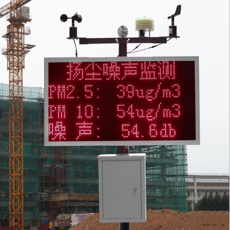
PM2.5 sensor and PM10 sensor dust monitoring system.jpg
Assign a permanent sensor serial number and a separate location identifier. The sensor travels; the location describes a particular exposure. If a unit moves from a loading area to a construction boundary, its history must show both deployments. Keeping the old location name because the modem stayed the same merges unlike observations and can make an installation change resemble a pollution trend.
For each position, record the inlet height, surrounding obstructions, nearest activities and intended question. A boundary location and a material-handling location need not produce equal concentrations. Consistent installation means documented, suitable exposure, not forcing every sensor into an identical but unsuitable position. Do not use one generic mounting height as a substitute for the site survey or project-specific requirements.
A dust monitoring system should distinguish sensor identity, station hardware and deployment period in its data structure. An illustrative calculation based on assumed site values, not a measured field record, shows why: 4 positions plus 2 relocations create 6 deployment records, even if only 4 sensors are owned. Label the extra deployments rather than purchasing unnecessary sensor identities or overwriting the original locations.
Which checks make a dust monitoring system comparable?
Use a common comparison location to test whether instruments agree before interpreting spatial differences. Arrange exposure so the units sample comparable air without obstructing one another. A comparison among sensors establishes relative agreement; it does not establish accuracy against an independent concentration reference. Include a suitable reference instrument when the measurement objective requires that additional link, and record the reference's own checks.
The NiuBoL PM2.5 sensor is a component choice for the particulate channel, not a complete network calibration procedure. Specify the supplied hardware and channel definitions when ordering matched units. Sensors with similar housings can still need individual evaluation. Do not transfer a correction merely because units share a brand, product family or connector.
Plan the comparison to cover relevant pollutant concentrations and weather, then keep a separate evaluation period. An illustrative calculation based on assumed site values, not a measured field record: a 96 h comparison at 15 min resolution yields 384 scheduled intervals; reserving 96 intervals for evaluation leaves 288 for developing a correction. Those counts are not a recommended minimum duration. A short comparison with little variation cannot characterize a different season.
Use a separate contiguous evaluation period rather than randomly distributing adjacent readings between development and evaluation. Check temporal autocorrelation before treating the holdout as independent; a time-ordered split alone does not establish independence. Inspect concentration range, temperature and humidity separately. A dust monitoring system that compares well during mild weather may fail when the aerosol or exposure changes. Flag unsupported conditions instead of extending a fitted relationship beyond the circumstances in which it was checked.
Work a calibration transfer before applying it remotely
The table is an illustrative calculation based on assumed site values, not a measured field record. It represents one PM channel during equal-duration, already aligned comparison intervals. Assume five development pairs give a candidate relationship: corrected concentration = 0.8 × raw concentration + 4 μg/m³. The coefficients belong only to this example; they are not NiuBoL factory settings.
| Pair | Use | Raw concentration (μg/m³) | Reference (μg/m³) | Corrected (μg/m³) | Corrected minus reference (μg/m³) |
|---|---|---|---|---|---|
| 1 | Development | 45 | 40 | 40 | 0 |
| 2 | Development | 70 | 60 | 60 | 0 |
| 3 | Development | 95 | 80 | 80 | 0 |
| 4 | Development | 120 | 100 | 100 | 0 |
| 5 | Development | 145 | 120 | 120 | 0 |
| 6 | Evaluation | 55 | 49 | 48 | -1 |
| 7 | Evaluation | 80 | 67 | 68 | +1 |
| 8 | Evaluation | 105 | 90 | 88 | -2 |
| 9 | Evaluation | 130 | 106 | 108 | +2 |
| 10 | Evaluation | 155 | 130 | 128 | -2 |
For evaluation pair 8, 0.8 × 10⁵ + 4 gives 88 μg/m³, leaving a residual of -2 μg/m³ against the assumed reference of 90 μg/m³. The negative sign means the corrected value is lower. Keep that sign convention in the commissioning sheet; otherwise technicians may apply an offset in the wrong direction when troubleshooting a station.
Across all five assumed evaluation pairs, including the extrapolated pair 10, mean absolute error is (1 + 1 + 2 + 2 + 2)/5 = 1.6 μg/m³. Their signed mean is -0.4 μg/m³, which is smaller because positive and negative differences cancel. Neither statistic is a measured product accuracy or proof that this correction transfers. Report both the evaluation conditions and the unmodified observations that produced them.
Pair 10 uses 155 μg/m³ raw concentration, beyond the development maximum of 145 μg/m³. It is deliberately an extrapolation check, not evidence that values above that range are qualified. The arithmetic produces 128 μg/m³, but a mathematically defined output is not a validated measurement. Record the condition and extend the comparison before authorizing that wider operating range.
When a station reaches its permanent location, compare it again under representative exposure. A dust monitoring system should retain an approval decision for each correction version and deployment, rather than copying a central equation across every device. The same slope and intercept can be inappropriate for a different aerosol, inlet arrangement or onboard processing revision, even when the communications settings match.
Installation handover must preserve the data contract
Verify the sensor supply, serial address and channel mapping locally before connecting the remote path. The NBL-1 RTU data collector supports serial acquisition and cellular communication; the supplied configuration still needs to be matched to the sensors. Confirm timestamp handling, register interpretation and failure indicators with the integrator. A live connection cannot establish that a concentration value has the correct scale.
Test the data contract with labelled commissioning messages that cannot be mistaken for environmental observations. An illustrative calculation based on assumed site values, not a measured field record: an agreed test register of 1376 with 0.1 μg/m³ per count must display 137.6 μg/m³. If it displays 1376 μg/m³, the scale is wrong by a factor of 10. This is not a supplied NiuBoL register definition.
Store the sample interval's start and end, not just the upload time. An assumed interval labelled 09:15 may mean 09:00–09:15 at one station and 09:15–09:30 at another, creating a 15 min mismatch. Time zones and daylight-saving rules must also be explicit. Reassigning timestamps until curves overlap hides the failure instead of repairing the shared time convention.
Install the units in their approved orientation and photograph the completed assembly before physical handover. Check the cabinet with doors shut and compare its actual arrangement with the approved drawing. Before you install a replacement enclosure, assess its effect on inlet exposure. Keep the dust sensor configuration details with the station record, but do not treat another product's protective enclosure as an approved replacement.
Handle missing intervals without rewriting history
A dust monitoring system needs separate states for valid observation, service, communication delay, invalid measurement and missing data. A delayed upload is not automatically a lost sample if acquisition occurred locally. Conversely, a healthy connection can deliver invalid values continuously. Report measurement validity and communications availability separately so that the maintenance team knows which part of the installation needs attention.
An illustrative calculation based on assumed site values, not a measured field record, uses a 2 h window with 120 scheduled one-minute observations. Suppose 102 arrive, of which 12 carry maintenance flags: 90 remain usable, or 75% of the schedule. Report received coverage as 85% and usable coverage as 75%; counting every received record as valid would conceal the service period.
Repeated uploads also need a stable observation key. If an assumed buffer retransmits 18 already stored rows, the 102 received observations must not become 120 distinct samples. Match records by sensor, deployment, channel and acquisition interval, then preserve the retransmission event separately if needed. Filling a gap with duplicated or interpolated values must not increase the count of measured observations.
Keep raw and corrected concentrations alongside the correction identifier. Never overwrite the original series when an equation changes. A revised analysis may generate a new derived series, but it should remain possible to reconstruct the earlier report. If a corrected value is outside its evaluation range, attach that limitation to the value rather than letting a visually smooth map imply uniform confidence.
When relocation or replacement breaks calibration transfer
Relocation changes the exposure record even if the electronics retain their calibration settings. Record when the old deployment ends and the new one begins. Assess the new inlet surroundings, aerosol sources and weather before accepting a transferred correction. A dust monitoring system cannot remove a real spatial difference simply by adjusting every station until it matches a central instrument elsewhere.
Replacement creates a different problem: the location remains, but the sensor response may change. Compare the incoming unit with a suitable reference or an established comparison arrangement before joining its data to the old series. Record the overlap and any discontinuity. An undocumented sensor swap can create a false trend that survives every later dashboard export because the location label never changed.
Treat revised firmware, changed fraction definitions and altered onboard compensation as reasons to review the processing chain. Do not stack a site correction on a revised factory correction without testing the combined result. Reject automatic transfer where the new conditions have not been evaluated; software availability is not measurement validity, and a fitted equation is not a certificate for every subsequent deployment.
Multi-station commissioning FAQ
Can identical PM sensors use one calibration equation?
Only after comparisons demonstrate that the shared equation is suitable for the individual units and intended conditions. A matching model name does not establish interchangeable response. Keep separate sensor identifiers and evaluation results, then document why a shared correction is acceptable. If evidence is absent, retain raw readings and withhold the unverified derived series.
Does a sensor-to-sensor comparison establish absolute accuracy?
No. Sensors can agree while sharing a common bias. A comparison against a suitable independent reference provides different evidence from agreement within a group. Identify the reference, its checks and the tested conditions. In the numerical example, the 1.6 μg/m³ evaluation error belongs to assumed pairs and is not an accuracy claim for supplied hardware.
Why keep an unused period for checking a correction?
An equation can match its development observations without representing later conditions. A separate evaluation period tests that limitation. The assumed planning example reserves 96 of 384 intervals, leaving 288 for development. Those counts do not qualify a duration; the withheld period must also cover relevant conditions and remain separate from the fitting decisions.
Should a moved station retain its previous location identifier?
Keep the permanent sensor serial number, but create a new deployment record linked to the new position. Record the move time, inlet exposure and any changed hardware. A correction may travel with the unit only after its applicability has been checked. Otherwise, a location change can appear as a concentration trend in the archived series.
How should maintenance data affect station coverage?
Separate received records from usable measurements. In the assumed two-hour example, 102 received observations include 12 maintenance records, leaving 90 valid observations from 120 scheduled intervals. The usable coverage is 75%, not 85%. Keep service flags attached to the original timestamps, and do not replace those observations with unlabelled estimates to improve the apparent coverage.
Can a corrected concentration replace the raw database value?
Retain both. Each corrected value should identify the equation, its version and the deployment for which it was approved. Overwriting the raw concentration prevents independent checking when a coefficient, firmware revision or installation condition changes. If a historical report is recalculated, issue a distinguishable derived version rather than silently changing the observations behind it.
Release each station with a traceable comparison
A multi-station dust monitoring system is ready for interpretation when each deployment has verified channel mapping, aligned intervals and an evaluated correction history. In the assumed example, 1.6 μg/m³ mean absolute evaluation error describes only five comparison pairs. Approve transfer at the destination using suitable additional observations, preserve the raw series and make unsupported conditions visible before comparing locations.
Use the NiuBoL contact page to share the station count, location plan, existing reference instrument and preferred data format. Include relocation expectations and responsibility for correction approval so the installation scope covers measurement records as well as hardware.









