







A wind speed alarm compares a defined wind measurement with an equipment-specific operating limit and activates an indication or control output. Correct settings require more than a speed threshold: the averaging period, sensor uncertainty, relay behavior and response to missing data must match the equipment manufacturer's instructions and the site's approved operating procedure.
Which measurement should trigger the wind speed alarm?
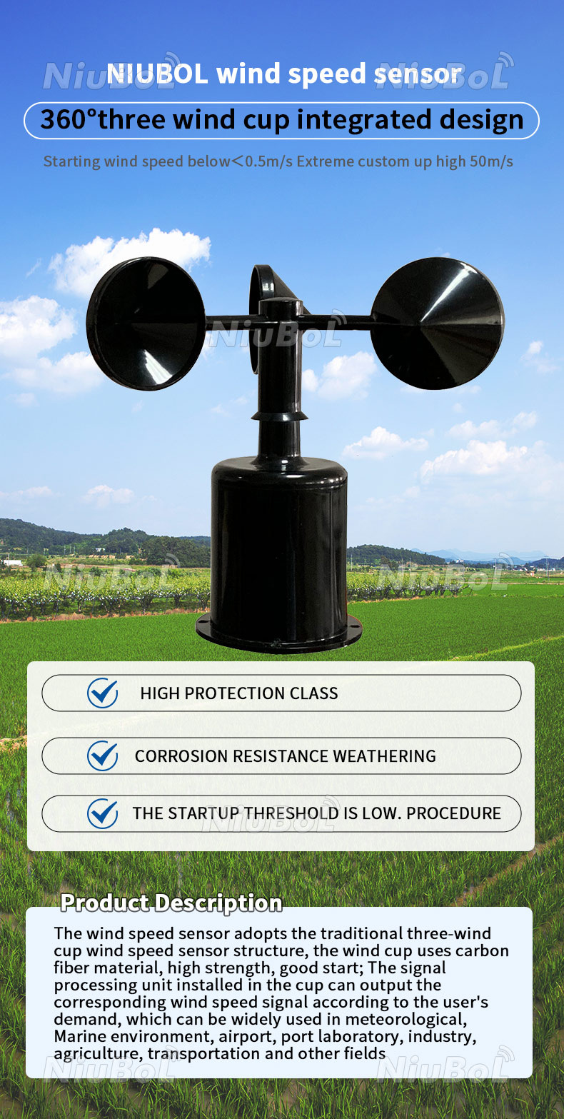
NBL-W-SS wind-speed sensing component; controller and alarm outputs are separate.
An instantaneous indication, a short moving average and a longer reporting average answer different questions. A display showing the latest sample does not necessarily show the quantity used by the alarm. Before entering a threshold, identify whether the equipment manufacturer specifies a gust, an averaging duration or another defined wind statistic. Do not translate an undefined word such as “maximum” into a controller setting without clarification.
Trace the measurement from the anemometer through signal conditioning, acquisition, calculation and relay output. A wind speed alarm can receive valid measurements yet make the wrong decision if its calculation differs from the equipment rule. Record the sampling interval and whether values are already averaged inside the sensor; averaging an averaged output cannot reconstruct the peaks that were removed upstream.
Unit conversion is another independent setting. Multiply a speed in m/s by 3.6 to obtain km/h. An assumed indication of 15 m/s therefore equals 54 km/h, not 15 km/h. Verify the units at the controller input, display, stored event and equipment instruction. Keep the original limit and its converted value together so a later operator does not convert it twice.
A short gust can disappear inside an average
The following sequence is an illustrative calculation based on assumed site values, not a measured field record. Assume equally spaced readings representing consecutive 1 s intervals, with no missing intervals. This simplified sequence tests calculation logic; it does not establish the dynamic response of an installed anemometer or reproduce every possible atmospheric fluctuation.
| Interval ending at (s) | Assumed interval speed (m/s) | Condition |
|---|---|---|
| 1 | 8 | Valid test input |
| 2 | 9 | Valid test input |
| 3 | 16 | Valid test input |
| 4 | 17 | Valid test input |
| 5 | 10 | Valid test input |
| 6 | 9 | Valid test input |
| 7 | 8 | Valid test input |
| 8 | 8 | Valid test input |
| 9 | 9 | Valid test input |
| 10 | 10 | Valid test input |
| 11 | 8 | Valid test input |
| 12 | 8 | Valid test input |
The 12 s mean is 120 / 12 = 10 m/s, while the largest individual interval value is 17 m/s. The largest consecutive 3 s mean is (16 + 17 + 10) / 3 = 14.33 m/s. These results describe the same input sequence, but they are not interchangeable alarm inputs. A controller that stores only the longer average loses the information needed to recover the shorter maximum.
For a logic test only, assume a comparator activates at or above 14 m/s. The 3 s average first reaches that value at interval 4: (9 + 16 + 17) / 3 = 14 m/s. The 12 s mean remains below it. This assumed threshold is not an operating recommendation; replace it with the OEM-defined limit and statistic before commissioning equipment.
Ask the integrator to replay this sequence through the actual calculation path and record the first activation timestamp. Specify how the moving window starts after boot and after a missing sample. Filling a missing interval with zero understates wind, whereas holding the previous value invents continuity. Either choice can change a wind speed alarm without changing the visible threshold.
Sensor accuracy is not the display increment
For the NiuBoL NBL-W-SS cup anemometer, the specified accuracy is ±(0.3 + 0.03V) m/s, where V denotes wind speed rather than electrical voltage. At an assumed 12 m/s operating point, the expression gives ±0.66 m/s. This is a specification-based calculation, not a complete uncertainty assessment of the mounted alarm system.
| NBL-W-SS item | Current specified value | Decision consequence |
|---|---|---|
| Measurement range | 0–45 or 0–70 m/s | Identify the ordered version |
| Displayable measurement resolution | 0.1 m/s | Resolution is not accuracy |
| Starting wind speed | ≤0.5 m/s | Not a gust-response specification |
| Current-output load | ≤250 Ω | Check the complete receiving circuit |
| Voltage-output load | ≥1 kΩ | Avoid an incompatible input load |
An assumed change from 12.0 to 12.1 m/s is only 0.1 m/s, smaller than the calculated ±0.66 m/s specification term at 12 m/s. Do not claim that every displayed increment represents a resolved change in site wind. Sensor exposure, rotor condition, calculation method and acquisition timing contribute additional limitations. The equipment owner must decide how those limitations affect its operating rule.
The NBL-W-SS provides wind speed, not an alarm relay or a safety-rated stopping function by itself. Available outputs include RS485, current, voltage and pulse versions; match the purchased configuration to the receiving instrument. If wind direction also matters, assess a combined ultrasonic wind sensor separately, without assuming that a different sensing principle automatically satisfies the required gust response.
Write the relay behavior before wiring it
A wind speed alarm relay needs a written state definition: normal operation, excessive wind, sensor fault, controller fault and power loss. Describe the field contact observed by the receiving equipment, not merely the controller's displayed status. “Normally closed” usually describes a contact with its coil de-energized; it does not by itself tell the operator which contact condition means permission to operate.
Separate the measurement decision from the electrical load. A relay suitable for a signal input may be unsuitable for directly switching a beacon, siren or contactor. Confirm contact voltage, current, load type and any required interposing equipment against the actual component ratings. Do not infer contact capacity from the anemometer's output specification or reuse a wiring sketch intended for a different alarm host.
Reset behavior also needs agreement. Acknowledging a sounder can silence an indication without restoring an operating permission. Confirm whether the alarm latches, who may reset it, and whether a restart requires deliberate action after acceptable wind returns. The equipment manufacturer defines any required restart delay; no universal delay follows from the wind sensor range or resolution.
Record a contact truth table on the panel drawing and verify it at the far end of the cable. A changed controller configuration can invert the effective permission even when all terminals remain untouched. Keep the configuration revision with the contact test results so a replacement controller is checked against the approved behavior rather than an old screenshot.
What should happen when the sensor stops reporting?
A zero reading and a missing reading must remain distinguishable. A motionless cup assembly can represent calm air, mechanical obstruction or a measurement fault. A communications timeout represents a different failure. The wind speed alarm should indicate invalid input separately and apply the equipment-specific fault response; neither a bright display nor a plausible retained value proves that new measurements are arriving.
As a separate assumed timing exercise, consider a receiver polling every 0.5 s with an independently configured data-age timeout of 2 s from the last accepted sample. The deadline equals 4 × 0.5 = 2 s, or four polling periods; it is not a delay inferred from four completed response timeouts. This proposed test configuration is not an NBL-W-SS feature or an approved machinery timeout.
Measure total response through the installed path rather than reporting that timeout alone. Sensor output update, receiver polling, calculation window, relay operation and downstream equipment reaction are different contributions. Some occur concurrently, so adding every nominal duration can also mislead. Test representative event timing and obtain the required sensor dynamic-response information when the equipment rule depends on a short gust.
Loss of controller power can remove the siren as well as the measurement. An energized permission relay can reveal some power failures, but that arrangement does not detect every cable fault, welded contact or software failure. Where the risk assessment requires an independent protective function, use the architecture and equipment specified by the responsible machinery designer; this monitoring arrangement carries no safety-certification claim.
Commission the calculation, contact and fault separately
Begin with the approved operating instruction and list the statistic, units, limit, reset conditions and fault response. Check sensor identity and mounting before testing the controller. Nearby structures can shelter the sensor or create disturbed flow; a low reading in such a location is not proof of low wind at the equipment. Confirm the representative position with the equipment supplier.
Use controlled signal simulation only through an approved test procedure with operating equipment isolated as necessary. Replay below-limit, equal-limit and above-limit inputs; then interrupt communication and controller power separately. Compare the calculated statistic, alarm status and physical contact with the expected states. A wind speed alarm test is incomplete when it verifies only that a lamp illuminates on the panel.
Retain the raw input sequence, timestamps, configuration export and receiving-contact observations. For remote records, distinguish local decision time from server arrival time. A compatible data logger can support recording when its selected inputs and timing suit the application, but a communications product is not evidence that the complete alarm chain has been validated.
Wind alarm setup FAQ
Can a 10-minute mean replace a short-gust alarm input?
Not unless the equipment instruction explicitly permits that statistic. A longer mean suppresses brief high readings and cannot reconstruct a shorter maximum after the underlying samples are discarded. Confirm the sensor output definition and the receiver's moving window together. Retain sufficiently detailed input data during commissioning to demonstrate the exact statistic used for the decision.
What wind speed should stop a crane or outdoor machine?
Use the equipment manufacturer's limit for the actual configuration and operating condition, together with the site's approved procedure. A limit for another machine, attachment or load is not automatically transferable. Confirm its units and averaging definition before programming the alarm. The illustrative comparator in this article must not be used as a machinery stopping threshold.
Does a 0.1 m/s display prove 0.1 m/s accuracy?
No. Resolution describes the reported increment, whereas accuracy describes a specified measurement limitation. For the NBL-W-SS expression, the term at 12 m/s is ±0.66 m/s before installation effects are considered. Check calibration condition, exposure and required decision uncertainty rather than setting an operating margin from the final digit on the display.
Should an RS485 timeout be treated as zero wind?
No. Zero is a possible measurement; a timeout means a fresh valid measurement was not received. Preserve the last value only with a visible age and invalid status, then apply the equipment's defined fault behavior. Test that response at the receiving contact, because the display and the output logic may handle missing data differently.
Does a normally closed relay make the installation fail-safe?
Not by itself. Contact terminology describes an electrical state, not the integrity of the whole protective function. Power failure, an open cable, a short circuit and a welded contact can produce different consequences. Verify the complete permission circuit against the machinery designer's fault requirements and avoid describing an ordinary monitoring relay as a certified safety function.
Can I test the alarm by turning the cups by hand?
Hand rotation can reveal a seized rotor or a changing indication, but it does not provide a known wind speed or prove gust response. Use it only as a permitted functional observation. Validate numerical processing with a controlled input and assess sensor measurement performance through the appropriate calibration or comparison procedure, following the instrument's maintenance instructions.
Hand over a defined alarm, not just a threshold
A wind speed alarm needs an OEM-approved wind statistic, valid measurements and a verified output response. The assumed sequence gives a 14.33 m/s maximum 3 s mean but a 10 m/s mean over 12 s, demonstrating why the averaging definition belongs in the handover record. Before operational use, confirm the mounting, calculation, contact states and fault tests with the responsible equipment team.
To discuss the measurement interface, send the equipment limit, averaging requirement and panel input details. Include the intended sensor position and required fault indication so the sensing and recording scope can be checked without confusing it with machinery safety approval.









