

— Blogs —
—Products—
 Consumer hotline +8618073152920
 WhatsApp:+8615367865107
Address:Room 102, District D, Houhu Industrial Park, Yuelu District, Changsha City, Hunan Province, China
Product knowledge
Time:2026-05-27 16:35:54 Popularity:464
This article is rewritten around the installation content in the supplied material. In online turbidity projects, the transmitter and probe are not installed simply by fixing them to a wall and powering them on. Installation position, sunlight, vibration, operator viewing height, wiring, immersion clearance, optical-window cleaning and calibration all affect whether the final NTU value can be trusted.
For system integrators, the installation procedure must be written into the construction and commissioning document. Otherwise, the same turbidity sensor may show unstable values because of bubbles, direct sunlight, poor cable waterproofing, wall reflection, sediment accumulation or incorrect RS485 polarity.
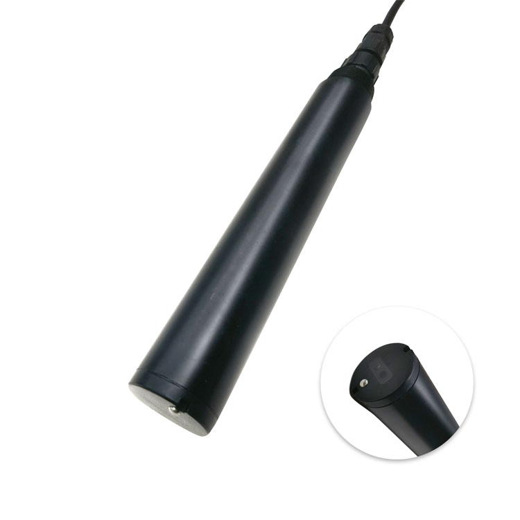
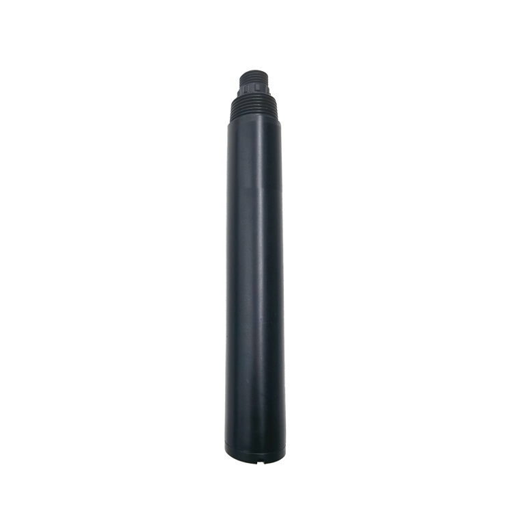
The online turbidity transmitter receives the turbidity signal and provides display, local operation and communication access. The NiuBoL NBL-WQ-TS probe measures turbidity by 90 degree scattered light and outputs RS485 Modbus RTU and 4-20 mA. The transmitter is usually mounted near the sampling point or inside a control cabinet, while the probe is installed in the tank, channel, sampling chamber or immersion pipe.
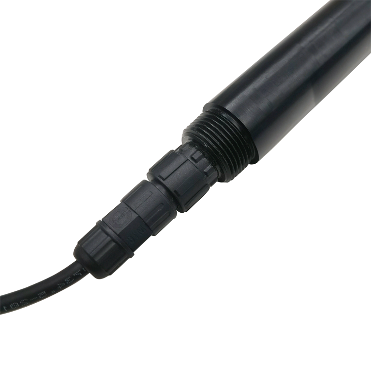
RS485 Modbus RTU wiring should be planned before installation. Red wire is power, black wire is ground, blue wire is 485A and white wire is 485B according to the NiuBoL wiring description. After wiring, check polarity and power voltage before energizing the system. For analog projects, 4-20 mA scaling should match the selected NTU range.
| Parameter | Specification |
|---|---|
| Model | NBL-WQ-TS online turbidity water quality sensor |
| Measurement principle | 90 degree scattered light method with built-in temperature measurement |
| Measurement range | 0-20.00 NTU, 0-100.0 NTU, or 0-1000.0 NTU |
| Accuracy | 卤3% or 卤1.5 NTU for 0-20.00 NTU; 卤3% or 卤2 NTU for 0-100.0 NTU; 卤5% or 卤3 NTU for 0-1000.0 NTU; temperature 卤0.3 C |
| Resolution | 0.01 NTU for 0-20.00 NTU; 0.1 NTU for 0-100.0 and 0-1000.0 NTU; temperature 0.1 C |
| Supply voltage | 12-24 VDC |
| Output signal | RS485 Modbus RTU and 4-20 mA |
| Power consumption | 0.2 W at 12 V |
| Protection rating | IP68 |
| Working condition | 0-50 C, pressure <0.2 MPa |
| Installation | Immersion installation, 3/4 NPT thread |
| Cable | Standard 5 m water-immersion cable, custom length available |
| Shell material | POM and ABS |
| Step | Installation requirement |
|---|---|
| 1. Confirm installation purpose | Determine whether the point monitors raw water, settled water, filtered water, secondary supply outlet or industrial process water. |
| 2. Select transmitter position | Avoid direct sunlight, strong vibration, dripping water and high-temperature equipment. Install slightly above operator eye level where possible. |
| 3. Reserve maintenance space | Keep enough space to open the transmitter enclosure, remove wiring covers and inspect terminals. |
| 4. Select probe position | Choose representative water flow. Avoid dead zones, bottom sediment, bubbles, wall reflection and debris impact. |
| 5. Keep immersion clearance | Keep the measurement end away from walls and bottom. Recommended clearance is more than 5 cm from side wall and more than 10 cm from bottom. |
| 6. Complete electrical wiring | Connect 12-24 VDC power, ground, 485A and 485B according to wire color. Check all terminals before power-on. |
| 7. Waterproof cable joints | All cable joints must be waterproof because the cable may be immersed or exposed to humid field conditions. |
| 8. Configure communication | Set Modbus address, baud rate, parity and polling interval. Verify data reading from PLC, RTU or gateway. |
| 9. Clean and inspect optical window | Before commissioning, check whether the optical window is clean and whether the cleaning tool is normal. |
| 10. Perform calibration | Use zero-turbidity liquid for zero calibration and standard solution for slope calibration after values stabilize for 3-5 minutes. |
After the instrument has been used for a period of time, the optical path window of the immersion turbidity sensor may become polluted. This creates measurement error. The source material recommends cleaning the optical window with alcohol cotton held by tweezers when necessary, and recalibrating after cleaning.
Do not disassemble the instrument. The probe contains sensitive optical and electronic components. Mechanical shock, cable pulling and unauthorized disassembly can damage performance.
Site environment challenge: operators need readable local display and reliable SCADA data.
System integration scheme: install the transmitter near the sampling location, avoid sunlight and vibration, and connect RS485 to SCADA.
User value delivered: commissioning personnel can compare local display and remote data.
Site environment challenge: limited space and high humidity make maintenance access difficult.
System integration scheme: mount the transmitter at a visible height and reserve cabinet-opening space.
User value delivered: maintenance teams can clean, calibrate and inspect wiring.
Site environment challenge: sediment, bubbles and wall reflection affect optical readings.
System integration scheme: install the probe with correct clearance and stable immersion depth.
User value delivered: the NTU value better represents the water body.
Site environment challenge: legacy systems may use analog input while new platforms need digital data.
System integration scheme: use RS485 Modbus RTU for gateway acquisition and 4-20 mA for old PLC input.
User value delivered: the project can upgrade data acquisition without replacing all hardware.
Accuracy selection: Match range to expected turbidity. Low NTU applications need a low range; high suspended solids require a wider range.
Communication selection: RS485 Modbus RTU is recommended for digital integration. 4-20 mA is retained for analog cabinets.
Installation environment selection: Avoid sunlight, vibration, bubbles, sediment, wall reflection and mechanical impact.
Power supply selection: Use regulated 12-24 VDC and check terminal polarity before power-on.
The installation record should include transmitter position, probe location, cable route, Modbus parameters, selected range, calibration liquid, calibration time and initial reading.
If the value is unstable after installation, first check bubbles, optical-window contamination, grounding, RS485 polarity, loose terminals and whether the measurement end is too close to the wall or bottom.
Q1: Where should the transmitter be installed?
Away from direct sunlight and excessive vibration, with enough space for enclosure opening and maintenance.
Q2: Where should the turbidity probe be installed?
At a representative water point away from sediment, bubbles, wall reflection and direct impact.
Q3: What clearance should be kept?
More than 5 cm from side wall and more than 10 cm from bottom where possible.
Q4: What wire colors are used?
Red is power, black is ground, blue is 485A and white is 485B.
Q5: When should the optical window be cleaned?
When readings drift, become unstable or after operation in dirty water for a period of time.
Q6: Why recalibrate after cleaning?
Cleaning changes the optical condition of the measurement window, so calibration verifies the reference.
Q7: What should procurement confirm?
Range, output, cable length, installation accessories, transmitter requirement and Modbus documentation.
Q8: Can it work with older PLCs?
Yes. RS485 supports digital systems and 4-20 mA can support legacy analog input.
The installation quality of an online turbidity transmitter determines whether turbidity data can be trusted. A project should purchase clear installation, wiring, cleaning and calibration requirements together with the sensor.
 NBL-WQ-CL Water Quality Sensor Online Residual Chlorine Sensor.pdf
NBL-WQ-DO Online Fluorescence Dissolved Oxygen Sensor.pdf
NBL-WQ-NHN Ammonia Nitrogen Water Quality Sensor.pdf
NBL-WQ-COD Online Water Quality COD Sensor.pdf
NBL-WQ-PH Online pH Water Quality Sensor.pdf
NBL-WQ-EC water quality conductivity sensor.pdf
Prev:Multi-Parameter Water Quality Analyzer for Water Treatment Process Monitoring and Control
Next:Conductivity Meter vs Conductivity: Difference, Measurement Logic and Online Sensor Integration
Related recommendations
Sensors & Weather Stations Catalog
Agriculture Sensors and Weather Stations Catalog-NiuBoL.pdf
Weather Stations Catalog-NiuBoL.pdf
Agriculture Sensors Catalog-NiuBoL.pdf
Water Quality Sensor Catalog-NiuBoL.pdf
Related products
 Combined air temperature and relative humidity sensor
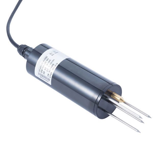 TDR Soil Moisture & Temperature Sensor for irrigation| RS485 |4-20mA| NBL-S-THR
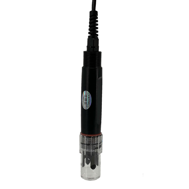 Soil pH sensor RS485 soil Testing instrument soil ph meter for agriculture |NBL-S-PH
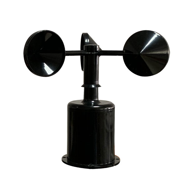 Wind Speed sensor Output Modbus/RS485/Analog/0-5V/4-20mA
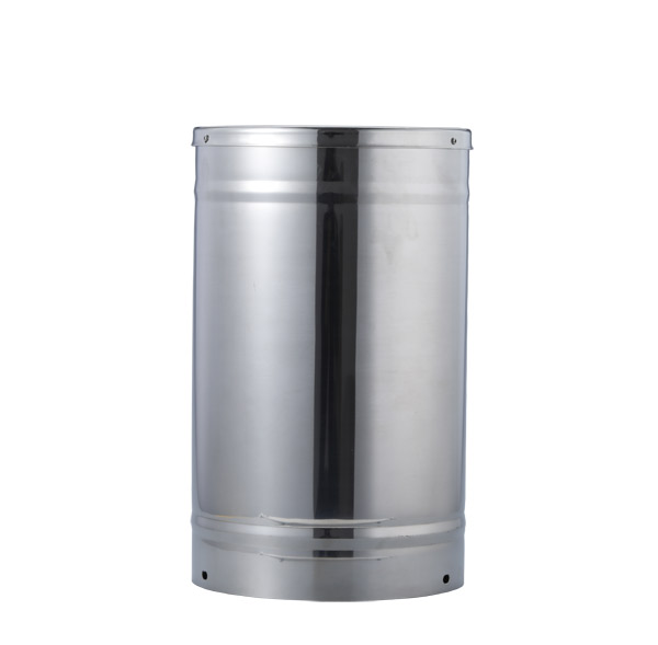 Tipping bucket rain gauge for weather monitoring auto rainfall sensor RS485/Outdoor/stainless steel
 Pyranometer Solar Radiation Sensor 4-20mA/RS485
Screenshot, WhatsApp to identify the QR code
WhatsApp number:+8615367865107
(Click on WhatsApp to copy and add friends)