





— Blogs —
—Products—
 Consumer hotline +8618073152920
WhatsApp:+8615367865107
Address:Room 102, District D, Houhu Industrial Park, Yuelu District, Changsha City, Hunan Province, China
Product knowledge
Time:2026-09-11 09:00:00 Popularity:206
Quick Answer: Install a pressure water level sensor at a known, stable elevation and keep its atmospheric reference dry and open when using a vented design. The sensor measures water above its diaphragm, not automatically the water-surface elevation. Set the range and PLC scaling for the ordered output, then compare the installed result with an independent level reference before using it for alarms or pump control.

A submerged pressure sensor infers liquid depth from hydrostatic pressure. For an open freshwater installation, h = p / (rho x g), where p is gauge pressure, rho is liquid density and g is gravitational acceleration. Using 1000 kg/m3 and 9.80665 m/s2, one metre of water corresponds to approximately 9.81 kPa. These are calculation assumptions, not a calibration certificate.
If the diaphragm elevation is 100.00 m relative to the project datum and measured depth is 2.30 m, water-surface elevation is 102.30 m. Moving the probe down by 0.20 m without changing its stored elevation creates an approximately 0.20 m reporting error even when the pressure measurement is correct. Secure the mounting and record the diaphragm reference, not only the cable entry location.
Density matters when measuring saline water, variable industrial liquids or a liquid whose temperature changes substantially. A transmitter calibrated as metres of water does not inherently correct for every process liquid. A pressurized tank introduces gas pressure above the liquid as well; an open-water gauge installation is not automatically an appropriate tank-level design.
A narrow well or covered sump may favor a submersible probe because no clear overhead measurement path is needed. Sediment, aggressive liquid or difficult recovery can favor a non-contact arrangement. The radar instrument shown below is an alternative technology, not the pressure sensor discussed in the installation procedure.
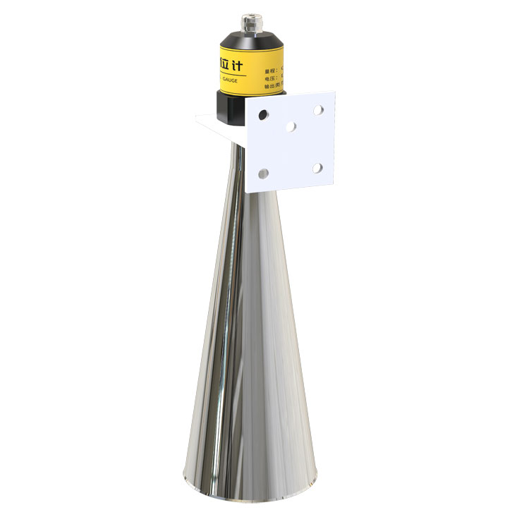
For an overhead instrument, review the measurement path, obstructions and sensor-to-surface distance. For a pressure probe, review the wetted materials, cable seal, vent and mounting elevation. These are different error mechanisms. Radar beam geometry and ultrasonic dead zones must not be copied into a pressure-probe acceptance test.
The NiuBoL NBL-L-SMP4603 is an analog-output submersible transmitter. Select its electrical version before panel wiring. A 4-20 mA input does not read RS485 messages, and the presence of RS485 elsewhere in the station does not give this probe a Modbus port.
| Item | NBL-L-SMP4603 selection data |
|---|---|
| Available depth spans | Spans from 0-1 mH2O up to 0-200 mH2O; select one ordered range |
| Accuracy | Typical +/-0.25% FS; maximum +/-0.5% FS |
| Current version | 4-20 mA; 9-30 V DC |
| Voltage versions | 0-5 V or 0-10 V; 12-30 V DC |
| Operating temperature | -20 to 85 C; compensated temperature -10 to 80 C |
| Protection and wetted materials | IP68; stainless-steel housing, 316L sensing element, fluororubber seals |
| Cable | Dedicated 7.5 mm polyethylene vented cable; order the required length |
Full-scale accuracy is tied to the selected span. For illustration, +/-0.5% FS on a 10 m span is +/-0.05 m, before datum, density, acquisition and installation effects. Choosing a 200 m range for a shallow sump sacrifices useful absolute accuracy; choose enough range for maximum submergence and credible transients without arbitrary oversizing.
For an illustrated 0-10 m, 4-20 mA configuration, h = (I - 4) / 16 x 10. A measured 12 mA represents 5 m above the diaphragm. The same current represents a different depth on another span. Enter both endpoints into the PLC and test the conversion; do not infer the range from the connector style.
Do not seal the atmospheric vent inside a pressure-tight potting joint. A sealed vent can make an otherwise working probe respond incorrectly to weather-pressure changes. A wet or blocked vent needs inspection; software offsets should not be used to hide a changing reference problem.
The overhead radar mounting drawing below uses a different reference: the surveyed elevation of the instrument's measurement plane minus its measured distance to water. Both methods need a stable datum, but their offsets have opposite meanings. Label distance, submerged depth and water-surface elevation separately in drawings and software.
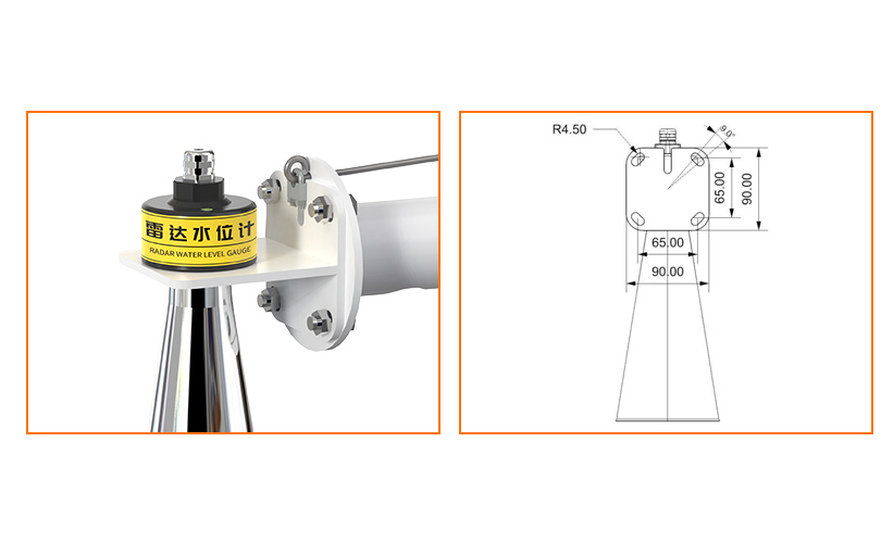
A vented gauge probe references the atmosphere through its cable. An absolute-pressure probe instead needs an appropriate atmospheric measurement and compensation method. For scale, an uncompensated pressure change of 1 kPa corresponds to about 0.102 m of freshwater under the assumptions above. First identify the pressure reference; do not label every slow drift as a defective sensor.
When readings disagree with a staff gauge, compare observation times and datums. Waves, pumping and a changed mounting point can create differences unrelated to calibration. If the liquid density used in conversion is 1000 kg/m3 but actual density is 1025 kg/m3, a true 2.0 m column generates pressure equivalent to approximately 2.05 m on that assumed-density scale.
Use any field zero adjustment only after the physical reference, atmospheric path, scaling and density assumptions have been checked. Record the adjustment and reason. Repeated offset changes can conceal a loose support or deteriorating vent condition.
The 4-20 mA circuit must supply the transmitter while driving the receiving input, cable resistance and any barriers or protection devices. The current-output version requires at least 9 V at the transmitter. At a 24 V supply, the simple remaining resistive budget at 20 mA is (24 - 9) / 0.02 = 750 ohms before additional device drops and design margin.
If the input burden is 250 ohms and round-trip cable resistance is 100 ohms, those two consume 7 V at 20 mA. Add the actual protection-device drops and verify the voltage at the probe during operation. Do not promise a universal cable distance from the words 4-20 mA alone.
If a submerged cable would be repeatedly damaged during sediment removal, consider a non-contact level instrument such as the arrangement illustrated below. Check access to its overhead mounting position and the unobstructed path to water before changing technology. Avoid transferring a difficult submerged maintenance task to an equally inaccessible overhead mount.
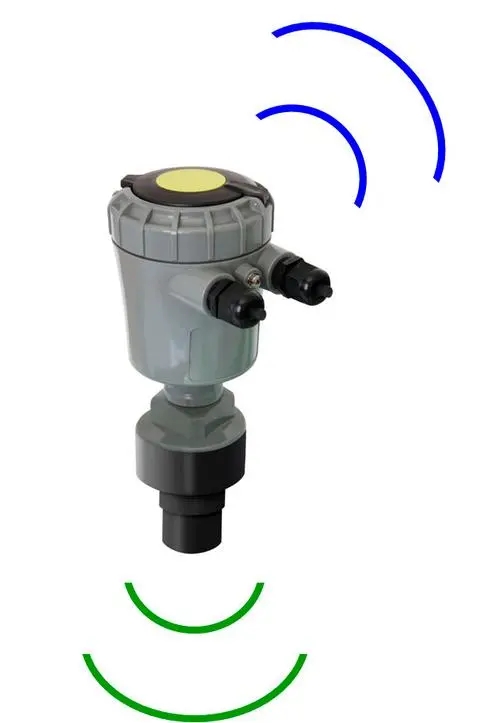
For remote monitoring, an analog input on the RTU or data logger converts the loop value, stores observations and passes data to a separate gateway. Where a project specifically requires an RS485 Modbus RTU pressure transmitter, select a documented digital model rather than assigning that protocol to the SMP4603.
Compare measured current, logger depth and datum-referenced water level. Where practical, check more than one known water level so that a span error is not mistaken for a zero offset. Record the liquid condition and reference method with the results.
| Symptom | Check before replacing the probe |
|---|---|
| Correct current, wrong displayed depth | PLC span, units, input type and datum offset |
| Slow weather-related disagreement | Gauge versus absolute design; vent condition or atmospheric compensation |
| Noise when a pump operates | Hydraulic location, power quality, cable routing and grounding |
| Step after maintenance | Diaphragm elevation, mounting movement and changed configuration |
| High or low signal outside normal operation | Wiring, supply and the documented fault behavior for the actual model |
Heavy deposits on an immersed pressure opening call for a cleaning and retrieval plan. Where that plan is impractical, an overhead radar instrument may reduce contact with the medium, provided the mounting and target conditions are suitable. Compare the cost of maintaining each installation, not just the probe prices.
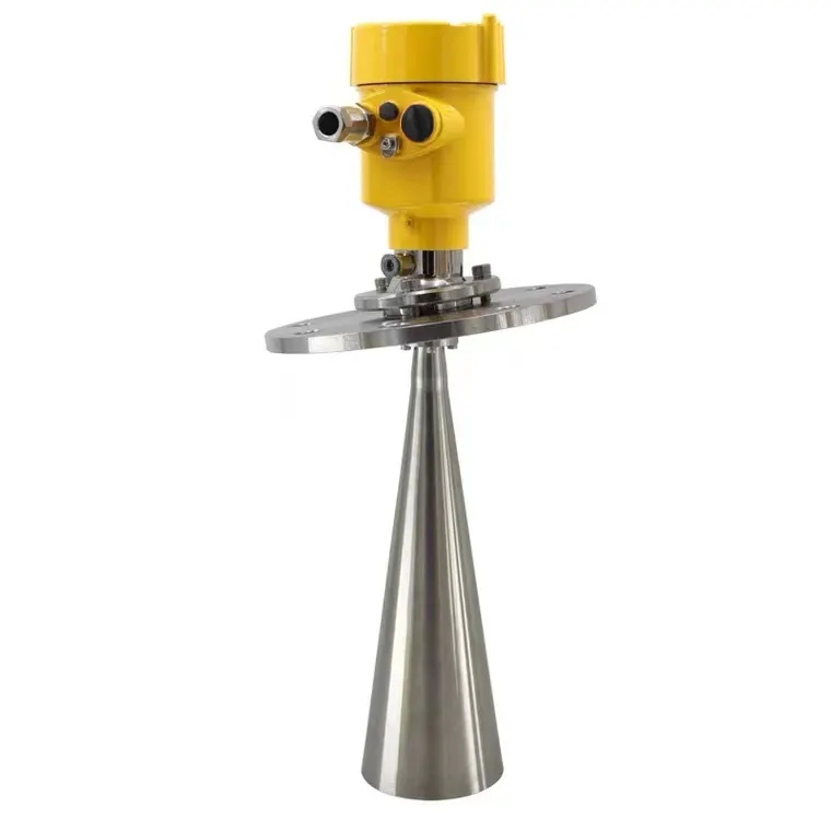
Define how the receiving system handles lost power, disconnected wiring and stale data. Do not assume every transmitter uses the same out-of-range fault current. Test the selected unit and input module, and mark invalid readings before they reach high-level or low-level alarm calculations.
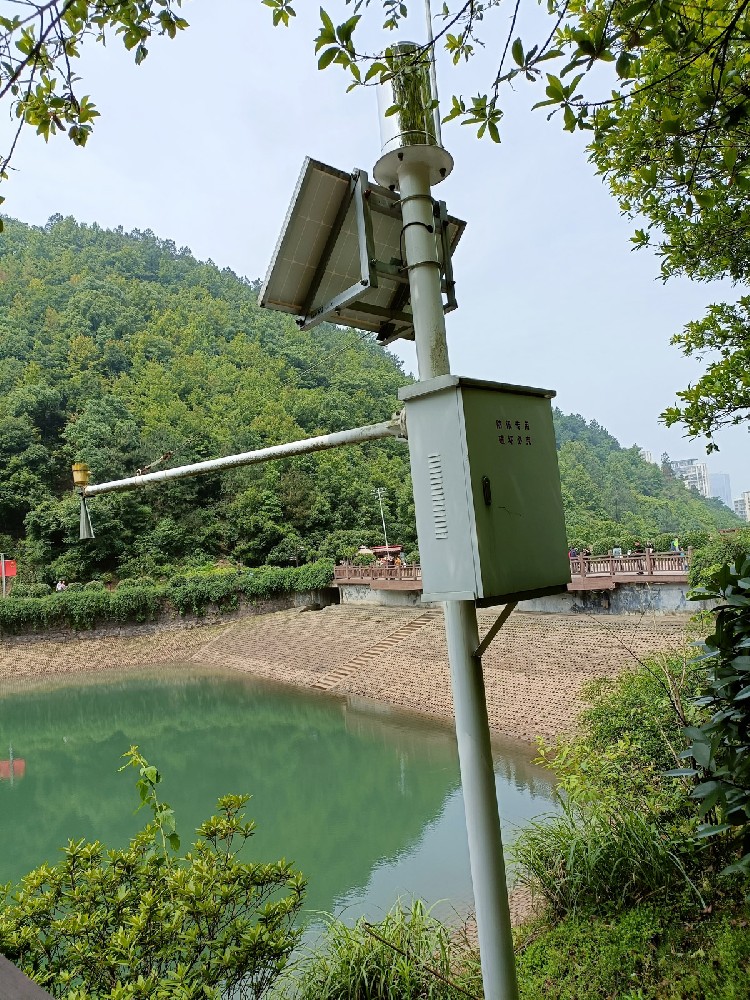
Where the level signal influences pumping, use the control and protection arrangements required by the process risk assessment. A monitoring article and an ordinary sensor specification do not establish a safety-rated protective function. A complete remote station also needs power, storage and communication; the field image below shows station-level hardware rather than a pressure probe alone.
At a known stable elevation, below the minimum level that must be measured and clear of sediment and direct hydraulic impact. Allow safe recovery and protect the dry vent termination. Record the diaphragm elevation relative to the same datum used by the display.
Not without preserving both electrical sealing and the atmospheric path. Order the required cable length where possible. A conventional waterproof splice can block the vent or introduce moisture even when the signal wires remain connected.
No. It normally reports the equivalent water depth above the sensing diaphragm. Add the surveyed sensor elevation to obtain water-surface elevation, using consistent units and a documented reference.
Not directly as a Modbus device. Use a compatible analog acquisition input or choose a pressure transmitter with a documented digital interface. Include any input module and configuration work in the quotation.
Send the medium, maximum submergence, required uncertainty, output, supply, cable length and installation drawing. Include the receiving input specification and any chemical or hazardous-area conditions. Ask for the exact configured model and applicable documentation rather than assuming options are standard.
Set an interval from site stability and measurement importance, then review it using inspection results. Recheck after maintenance, flooding, support movement or unexplained drift. A fixed annual interval is insufficient where sediment or mounting changes occur more often.
A pressure water level sensor gives useful depth data when its mounting reference, atmospheric compensation and input scaling are controlled. Select the range around the real water column, verify the installed system against an independent reference, and keep vent maintenance accessible. NiuBoL can assess the transmitter and logger combination from the site's depth envelope and electrical input requirements.
Prev:Small Weather Station Installation: Siting, Mast and Commissioning
Next:Saline Soil Monitoring System: Profile Layout and Installation
Related recommendations
Sensors & Weather Stations Catalog
 Agriculture Sensors and Weather Stations Catalog-NiuBoL.pdf
Weather Stations Catalog-NiuBoL.pdf
Agriculture Sensors Catalog-NiuBoL.pdf
Water Quality Sensor Catalog-NiuBoL.pdf
Related products
 Combined air temperature and relative humidity sensor
 TDR Soil Moisture & Temperature Sensor for irrigation| RS485 |4-20mA| NBL-S-THR
 Soil pH sensor RS485 soil Testing instrument soil ph meter for agriculture |NBL-S-PH
 Wind Speed sensor Output Modbus/RS485/Analog/0-5V/4-20mA
 Tipping bucket rain gauge for weather monitoring auto rainfall sensor RS485/Outdoor/stainless steel
 Pyranometer Solar Radiation Sensor 4-20mA/RS485


Screenshot, WhatsApp to identify the QR code
WhatsApp number:+8615367865107
(Click on WhatsApp to copy and add friends)

