

— Blogs —
—Products—
 Consumer hotline +8618073152920
 WhatsApp:+8615367865107
Address:Room 102, District D, Houhu Industrial Park, Yuelu District, Changsha City, Hunan Province, China
Product knowledge
Time:2026-09-11 10:00:00 Popularity:173
Quick Answer: A saline soil monitoring system needs paired water-content and conductivity measurements at defined depths, with irrigation and drainage records to explain changes. Start with management zones and a soil profile, then allocate probes, power and data channels. A salt-related reading alone cannot establish nutrient availability, sodium hazard or the water volume needed for reclamation.
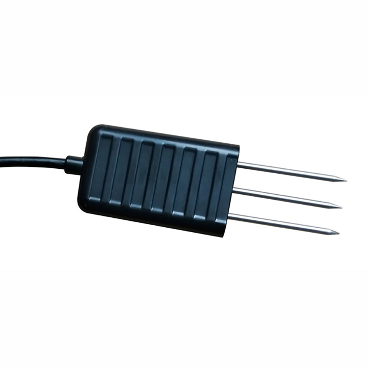
Salt-affected fields rarely behave as one uniform block. A poorly drained low area, a coarse-textured strip and a field supplied by a different irrigation source can respond differently to the same irrigation schedule. Installing one convenient probe beside the control cabinet hides those differences rather than measuring them.
Begin with a map of irrigation sectors, elevation, soil texture and drainage. Use an initial survey and soil sampling to decide which areas can share an interpretation. Then select profile positions that represent those areas. A permanent station should follow an explicit monitoring question, such as whether a leaching treatment moves salt below the active root zone or whether a low-lying sector remains wet while EC rises.
The FAO discussion of saline-soil management explains why reclamation depends on soil condition, the target depth and drainage as well as applied water. A monitoring system can document a response; it cannot provide a universal leaching prescription from an EC threshold.
| Project question | Measurement needed |
|---|---|
| Did water reach the monitored layers? | Time-aligned volumetric moisture at selected depths, plus irrigation and rain records |
| Did salt-related conditions change? | EC and salinity trends interpreted with moisture, temperature and the measurement method |
| Is irrigation water adding salts? | Water-source EC and an appropriate water-quality analysis; soil EC is not a substitute |
| Is sodium affecting soil behavior? | Relevant laboratory chemistry and soil assessment; a bulk EC value does not identify sodium hazard |
| Which fertilizer or amendment is required? | Crop requirements and suitable nutrient or soil analyses, not an inferred NPK result from conductivity |
Keep the term fertility tied to an actual measurement method. If the installed package measures only moisture, temperature, EC and salinity, label those four quantities on the dashboard. Do not rename a conductivity channel as nitrogen, phosphorus or potassium, or claim that a salinity value diagnoses every type of salt-affected soil.
A simpler temperature and moisture probe can be useful at an additional reference point where no EC measurement is required. It does not become a four-parameter salt probe because it uses a similar housing or connector.
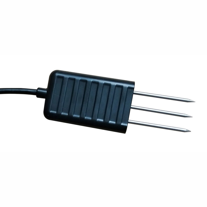
Consider an illustrative installation with three management zones and three depths per zone. It needs nine four-parameter probes, producing 36 measurement channels. It does not need 36 separate probe addresses if each instrument reports its four channels together. The chosen depths must come from the crop and soil profile; the example is a channel calculation, not a fixed planting recommendation.
Give every channel a location identity that survives a hardware replacement. For example, zone B, profile 2, depth 40 cm should remain the same logical point even if a replacement probe has a different serial number. Keep the physical serial number, bus address and installation date as associated records rather than using the serial number as the only location label.
| Layout item | What to fix before installation |
|---|---|
| Profile position | Coordinates, irrigation sector, emitter or furrow offset, texture and drainage context |
| Depth | Actual electrode depth and the layer it is intended to represent |
| Reference observations | Rain, irrigation timing and volume where measured, water source and fertilizer events |
| Network branch | Probe address, cable length, nearest junction and logger port |
| Comparison method | Soil-sampling location, extraction procedure and the conditions under which results will be compared |
A portable survey helps locate contrasts before committing to buried cables. Keep that survey's sampling method separate from permanent-station records. The Android-connected instrument below is a survey option, not the data logger or communication interface built into every fixed probe.
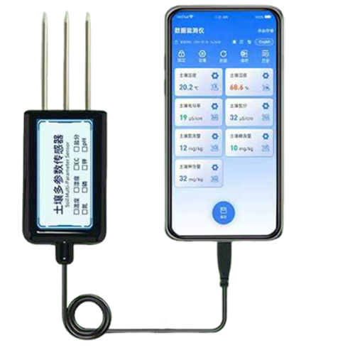
The NiuBoL NBL-S-TMCS is one option for paired measurements at each point. Its moisture channel uses FDR and its EC channel uses an AC bridge method. The following specifications describe the probe, not the complete station or a laboratory soil test.
| Item | NBL-S-TMCS value |
|---|---|
| Temperature | -40 to 80 C; accuracy +/-0.5 C; resolution 0.1 C |
| Volumetric moisture | 0-100%; resolution 0.1%; nominal accuracy 5%, with the applicable basis to be agreed for the soil |
| EC | 0-10000 uS/cm; resolution 1 uS/cm; specified accuracy +/-5% |
| Salinity output | 0-8000 mg/L; resolution 1 mg/L |
| Power and interface | DC 5-24 V or DC 12-24 V version; RS485 Modbus RTU |
| Protection and environment | IP68 probe; operating environment -40 to 85 C |
| Materials and cable | Special corrosion-resistant electrodes, epoxy sealing; standard 5 m cable |
The EC upper limit is 10 mS/cm after unit conversion. Check the expected measurement range during the initial survey; a sensor that saturates cannot show the magnitude of a higher-EC condition. Confirm maximum current and cable-sheath suitability for the delivered version before calculating the power system or ordering long extensions.
Do not directly compare in-situ readings with a laboratory threshold defined for a different extraction method. Keep the laboratory quantity, units and temperature reference attached to the result. Use soil samples to establish the relationship needed for the project rather than applying an undocumented conversion factor.
Open the access pit beside the profile and place electrodes into undisturbed soil at each selected depth. Avoid locating every probe inside loose backfill. Backfill the pit and cable route carefully so installation disturbance does not become a preferential water path through all monitored layers.
Survey each depth after placement and photograph the arrangement before covering it. Protect cable exits from cultivation and mark the profile where operators can find it without disturbing the sensing area. Allow a stabilization period in the record, especially if soil has been unusually wetted or compacted during installation.
In greenhouse beds, compare equivalent positions relative to drip lines and plant rows. In reclaimed open fields, keep a contrasting untreated or differently managed area where the study design requires one. A reference profile is useful only when differences in soil and irrigation are understood; it is not automatically a calibration standard.
Connect the probes to an RS485 Modbus RTU master in a field logger or RTU. For the NBL-S-TMCS, use 9600 bps, 8 data bits and no parity, with at least 1000 ms between communications. Confirm firmware-specific decoding and the stop-bit setting before installing multiple instruments. Give every probe a unique address and test the mapping against its physical depth.
Keep acquisition and upload intervals distinct. With the illustrative 36 channels sampled every 15 minutes, there are 96 sample times and 3456 channel values per day, before status and event records. An hourly upload can carry those observations without replacing them with one hourly snapshot, provided the logger stores and transmits the original timestamps.
Add irrigation start and stop times, fertilizer applications, rainfall and drainage observations to the same time basis. Record changes in water source. Otherwise a rising EC trace may be discussed as a soil-treatment failure when the actual change was a different irrigation-water supply.
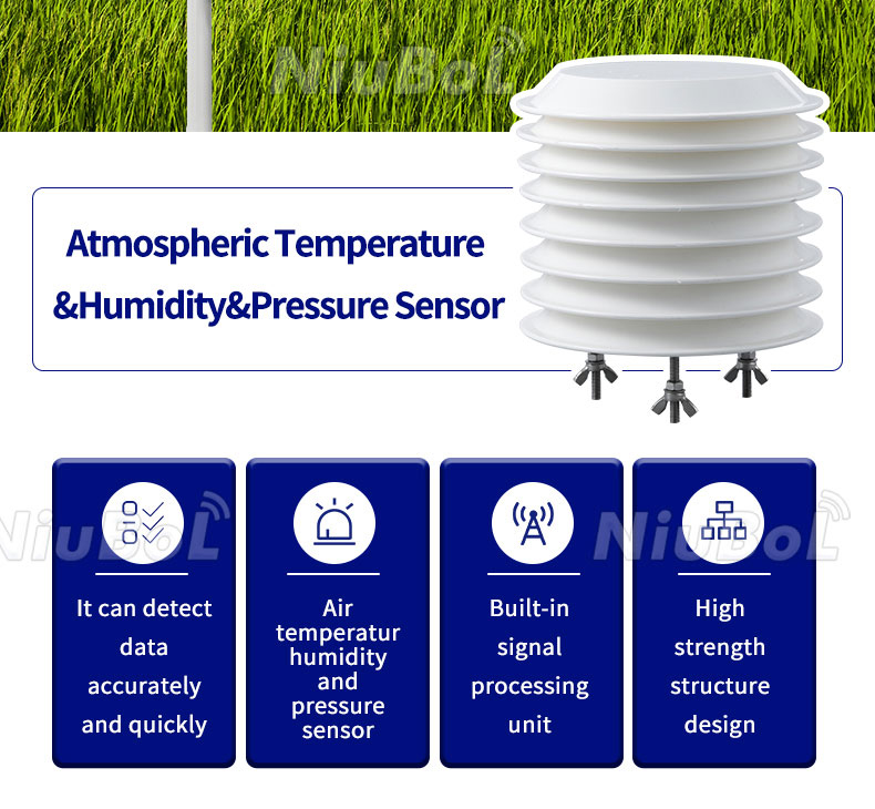
Atmospheric temperature, humidity and pressure can provide environmental context, but they are separate from the buried profile. The louvered sensor below does not measure soil water or salinity.
After an irrigation event, first check the moisture response and the sequence of changes with depth. Then review the EC trace under comparable water conditions. A lower shallow reading immediately after wetting can reflect dilution; it is not, by itself, proof that salt has left the root zone.
A delayed change at a deeper probe may support an interpretation of redistribution, but point sensors do not measure the total salt mass leaving the field. Where the decision requires a salt balance, additional water volumes, drainage chemistry and soil sampling are needed. Keep that distinction explicit in project acceptance criteria.
Commissioning should demonstrate correct channel-to-depth mapping, units, timestamps, missing-data flags and a plausible response to a recorded field event. Agree laboratory comparisons separately. Do not use the same pass/fail tolerance for a point probe, a composite soil sample and a drainage-water sample.
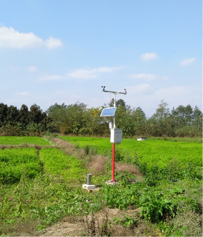
Base the number on independent soil, irrigation and drainage zones. Start with a survey, then place profiles where each distinct condition needs its own management interpretation. A fixed number per hectare cannot account for those differences.
Only quantities supported by the installed instruments should be reported. The NBL-S-TMCS supplies moisture, temperature, EC and salinity. Nutrient recommendations and sodium-related assessments require additional methods; they cannot be derived reliably from EC alone.
No. It observes conditions around that probe. Evaluate the depth sequence, drainage and an appropriate sampling program if the project needs to demonstrate removal rather than local redistribution or dilution.
Only when the project also specifies the controller, valves, operating limits and fault response. Monitoring can remain advisory. A salinity alarm should not start unlimited irrigation where drainage capacity or water availability is uncertain.
Provide the zone map, profile depths, expected EC, cable distances, power locations and data destination. Identify whether the scope includes a survey, probes, logger, gateway, installation or ongoing sampling. These items affect the price independently.
Possibly, but channel count alone is not enough to decide. Review route length, topology, supply drop, electrical exposure and recovery from a branch fault. Separated field areas may be better served by several local loggers with a common data platform.
A saline soil monitoring system is useful when its spatial layout and event record explain the management treatment. Select the probe range after a survey, protect the soil profile during installation and distinguish observed salt-related trends from laboratory classifications. Send NiuBoL the zone layout and depth schedule to assess probe quantities, acquisition hardware and communication options.
Prev:Pressure Water Level Sensor: Installation and Operating Procedure
Next:Rainfall Monitoring Station for Smart Agriculture: Irrigation Decisions
Related recommendations
Sensors & Weather Stations Catalog
 Agriculture Sensors and Weather Stations Catalog-NiuBoL.pdf
Weather Stations Catalog-NiuBoL.pdf
Agriculture Sensors Catalog-NiuBoL.pdf
Water Quality Sensor Catalog-NiuBoL.pdf
Related products
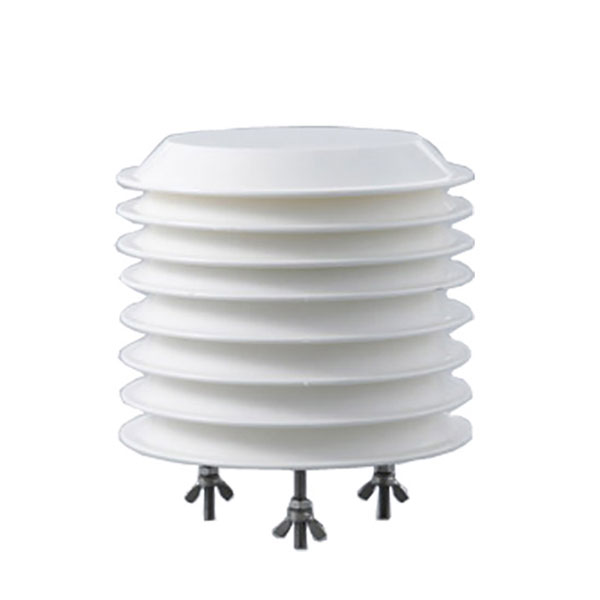 Combined air temperature and relative humidity sensor
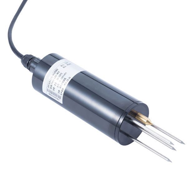 TDR Soil Moisture & Temperature Sensor for irrigation| RS485 |4-20mA| NBL-S-THR
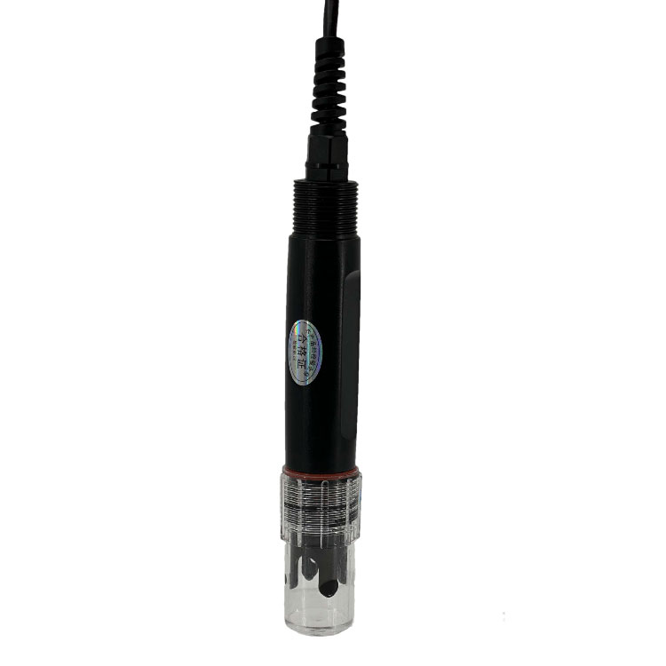 Soil pH sensor RS485 soil Testing instrument soil ph meter for agriculture |NBL-S-PH
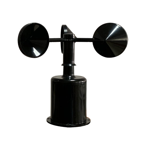 Wind Speed sensor Output Modbus/RS485/Analog/0-5V/4-20mA
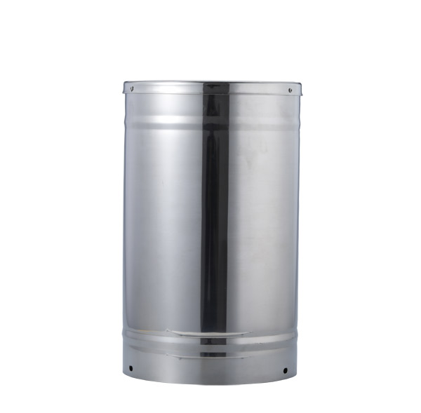 Tipping bucket rain gauge for weather monitoring auto rainfall sensor RS485/Outdoor/stainless steel
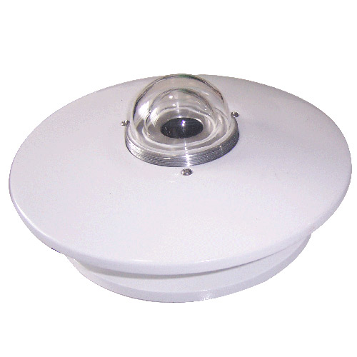 Pyranometer Solar Radiation Sensor 4-20mA/RS485

Screenshot, WhatsApp to identify the QR code
WhatsApp number:+8615367865107
(Click on WhatsApp to copy and add friends)