

— Blogs —
—Products—
 Consumer hotline +8618073152920
 WhatsApp:+8615367865107
Address:Room 102, District D, Houhu Industrial Park, Yuelu District, Changsha City, Hunan Province, China
Product knowledge
Time:2026-09-09 09:00:00 Popularity:241
Quick Answer: Radar water level sensor installation depends on four checks: a surveyed reference point, clearance above the highest water surface, an unobstructed beam at the lowest water level, and correct distance-to-level conversion. A stable number on the screen proves none of these by itself. Verify the raw distance and the calculated water level separately before connecting the measurement to operational alarms.
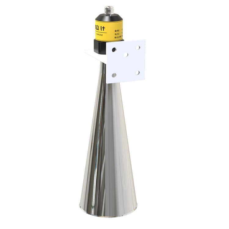
The datum is the reference used to express water level. It may be a local gauge zero or a surveyed elevation system. The radar measures a distance from its own reference point; it does not know the site's elevation merely because the enclosure is mounted on a pole.
For a vertically mounted sensor reporting unadjusted distance, water-surface elevation equals sensor-reference elevation minus measured distance. If the reference elevation is 104.250 m and distance is 3.180 m, the water elevation is 101.070 m. If local gauge zero is 98.000 m, the corresponding gauge height is 3.070 m. Keep elevation and gauge height in separate tags, with units and datum names.
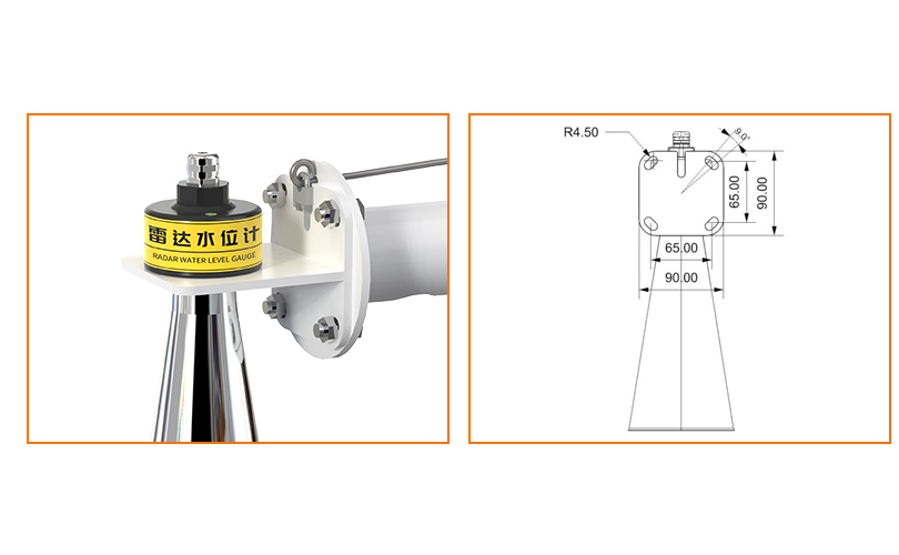
Locate the radar's actual ranging reference on its dimensional drawing. The bottom of the bracket, threaded shoulder and antenna face are not necessarily the same reference. A distance offset already applied inside the instrument must be accounted for in the logger calculation. Applying the same offset twice produces a consistent error that can look convincing on every display.
Tie the installation to a stable benchmark that can be checked after flooding or maintenance. Record the reference elevation and the physical point used to establish it. Replacing the bracket, moving the sensor or changing its offset requires another reference check; replacing only the communications cable normally does not.
The highest water surface is closest to the antenna and determines near-field clearance. The lowest water surface is farthest away and determines range and beam footprint. A bracket chosen from today's water level can fail at either extreme.
For an illustrative installation, suppose the antenna reference is 4.50 m above gauge zero and the design high-water level is 4.10 m. The remaining distance is 0.40 m. Against a 0.15 m minimum measuring distance, that leaves 0.25 m before considering waves, structural movement and the project's required allowance. It does not automatically establish an acceptable flood clearance.
Check whether floating debris, overtopping water or ice could reach the instrument even when the nominal level remains outside the blind zone. IP67 is an ingress-protection rating, not an instruction to install the radar where flood debris can strike it. Provide safe access for inspection without requiring personnel to work over hazardous water.
The sensor must see the intended water target through the full level range without bridge beams, banks or turbulence entering the measurement cone. For an ideal cone with full beam angle theta, approximate footprint diameter is D = 2 x L x tan(theta/2), where L is the distance from the antenna to a perpendicular target plane.
For an 8-degree beam at 10 m, D is approximately 1.40 m. At 20 m, it is approximately 2.80 m. These are geometric estimates, not sharp boundaries beyond which reflections become impossible. Allow additional clearance and inspect the actual echo behavior where strong reflectors are nearby.
At low water, a sloping bank can enter the wider footprint even though the beam is clear at normal level. On a bridge, check cross-members beneath the proposed mounting point, not just the view from the deck. Include vegetation that may grow or move into the path during the monitoring season.
For the vertically directed level sensor discussed here, keep the antenna axis perpendicular to the nominal water surface. Tilting it away from an obstruction can move the target onto a bank and weaken the water return. Move the mounting point or select a suitable antenna arrangement instead of treating arbitrary tilt as a general solution.
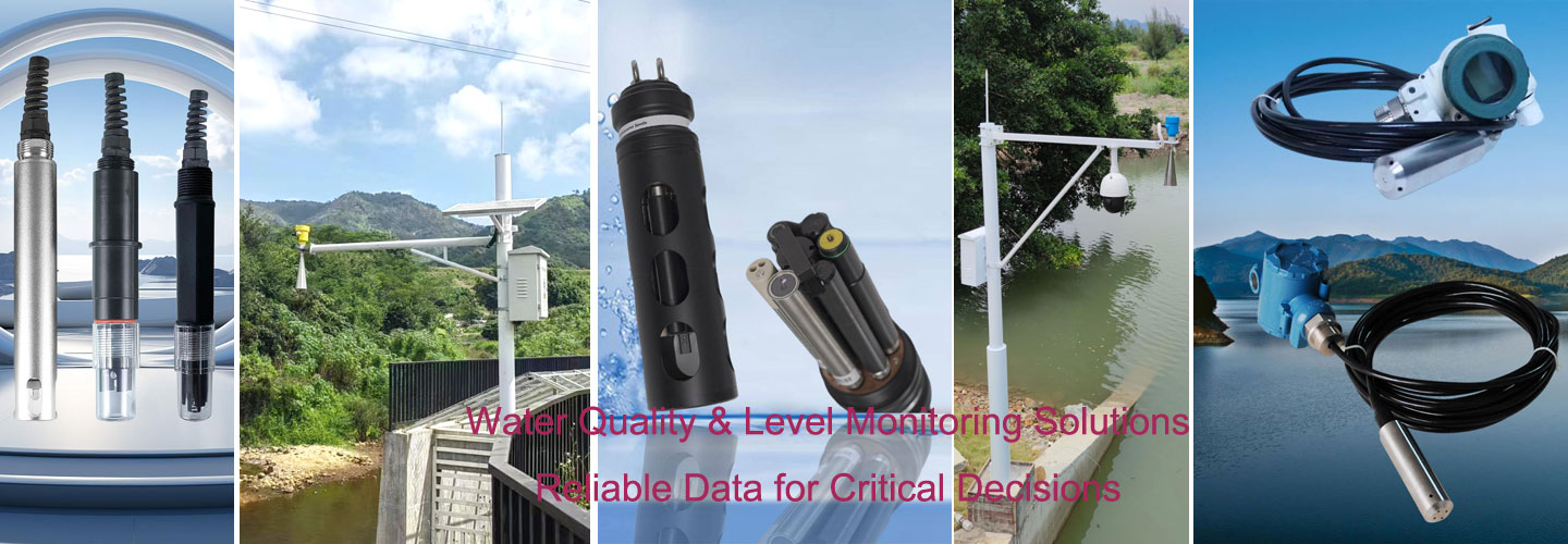
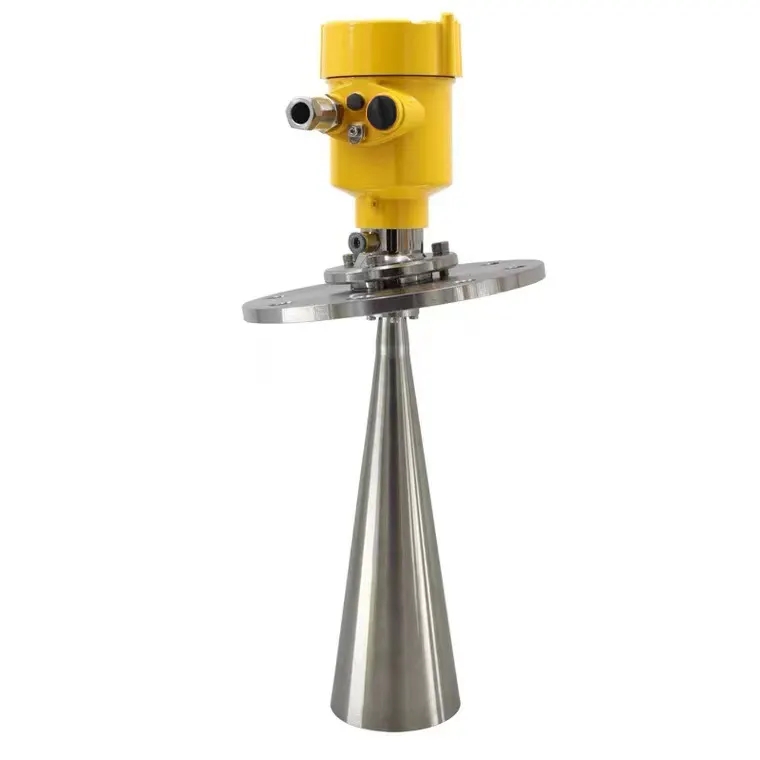
The NiuBoL 77-79 GHz river water level sensor is one configuration for non-contact monitoring. Its limits below apply to that configuration, not every horn, lens or other non-contact instrument pictured on this page.
| Parameter | 77-79 GHz configuration | Installation consequence |
|---|---|---|
| Measuring distance | 0.15-65 m | Check maximum and minimum water levels from the antenna reference. |
| Accuracy and resolution | Accuracy +/-1 mm at 4 m, 25 degrees C and 40% RH; resolution 1 mm | Datum, waves and mounting errors are additional. Do not treat this test condition as a whole-site accuracy guarantee. |
| Beam angle | 8 degrees | Calculate clearance at the longest operating distance. |
| Supply and power | 10-30 V DC; maximum 0.6 W | Include cable drop and the separate logger and modem loads. |
| Communication | RS485 Modbus RTU; default 9600 bit/s, 8 data bits, no parity, 1 stop bit | Configure the receiving port and identify distance versus level registers. |
| Environment | -40 to 80 degrees C; 0-95% RH, non-condensing; IP67 | Protect connections and assess condensation and flood exposure. |
Specify cable length, sheath suitability and the connector arrangement with the installation. A range specification does not define the allowable cable length. For an exposed bridge or riverbank, surge protection and bonding need to be designed with the station's power and communications routes, not inferred from the sensor's IP rating.
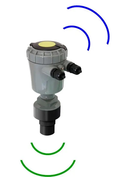
First confirm that the instrument can see the water. Set the measurement range to cover the actual distance envelope with the appropriate allowance. A range set too short can reject the real water echo during low water. An unnecessarily broad search range can admit avoidable reflections from more distant objects.
If false-echo suppression is available, use it only after identifying the unwanted reflector and following the procedure for that firmware. Do not teach the instrument to suppress the current water surface. Save the original settings and compare the echo curve before and after any adjustment.
Filtering should smooth unwanted wave variation without hiding the level changes the project needs to detect. Test the selected damping against a representative rate of change. A smooth graph is not sufficient evidence of good measurement if a rising water level appears late.
The hydrological logger should retain measurement quality or fault information where available. A failed echo, a value outside the configured range and a communication timeout are different events. None should silently become a zero water level or an indefinitely repeated last value.
Bench-test the radar with the intended RTU or data logger before installing it over water. Use the actual supply and a suitable target within the measuring range. Check more than one distance to distinguish an offset from a scale error. This is a functional check, not a substitute for a traceable calibration where one is required.
For Modbus RTU, confirm the device address, serial settings, function and register interpretation. The distance may be represented in centimeters or millimeters depending on the register. A value of 3180 interpreted as centimeters instead of millimeters produces a tenfold error. Verify the raw value and engineering unit before entering a datum formula.
Test the direction of change: when the water rises, downward-looking radar distance decreases while calculated water level increases. If both increase together, inspect the calculation and the selected register. Also check whether the sensor is already reporting a configured level rather than raw empty distance.
| Observed behavior | Check first | Useful distinction |
|---|---|---|
| Constant disagreement with a staff gauge | Datum, radar reference point and offsets | A fixed offset differs from a range-dependent error. |
| Disagreement changes with level | Scaling, target selection and geometry | Check several levels rather than correcting one reading. |
| Jumps only at low water | Bank or structure entering the larger footprint | The same mounting can be clear at high water and obstructed at low water. |
| Level freezes during a rapid rise | Minimum clearance, range limits, damping and stale-data handling | A frozen display can conceal an invalid echo or a communication fault. |
| Change follows maintenance | Bracket movement, reference adjustment or configuration replacement | Re-survey before changing the level offset to match expectations. |
For field comparison, read the reference gauge at nearly the same time and at a location representing the same water surface. Upstream and downstream of a constriction can have different levels. Average wave effects consistently and record the observed conditions instead of demanding that unrelated instantaneous readings agree exactly.
Keep the sensor face, bracket and beam path inspectable. Check for deposits, nesting, loose fasteners and damaged cables after severe weather. A replacement unit should be checked against the existing benchmark before its data are joined to the old record.
For installation support from NiuBoL, send a side-view drawing with high and low water levels, proposed sensor reference elevation, nearby structures and cable routing. Include the required level datum and receiving-system interface. Those details allow a meaningful review of mounting height and antenna selection before steelwork is fabricated.
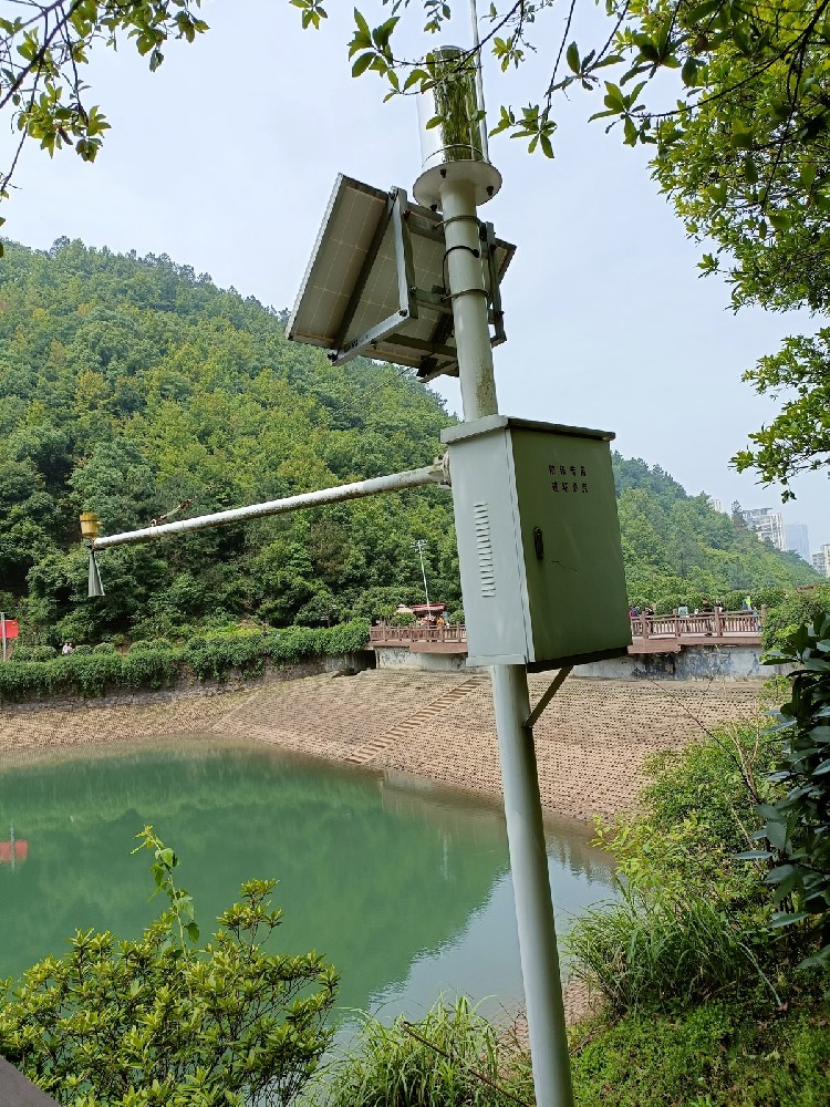
An offset can account for a known reference difference. It cannot correct an obstructed beam, changing bracket movement or a wrong scale factor. Verify geometry and distance first, then apply the documented datum conversion once.
It is a measurement limit for the specified configuration, not a complete flood-clearance allowance. Add the project's allowance for waves, debris, structural movement and installation tolerance. If that cannot be achieved, revise the mounting arrangement or instrument selection.
Not automatically. Mounting threads, antenna geometry, weight, reference position and beam angle differ. Check the actual dimensional drawing and keep the antenna's field of view clear after the final bracket and cable are fitted.
First identify its source. A fixed obstruction may require relocation; a moving object may not be removable by a static suppression map. Filtering can also delay real level changes. Validate the result across the operating range rather than accepting a quiet display.
A stable surveyed reference and a suitable comparison method are needed to establish and recheck the installation. A staff gauge can be useful where it is safely readable and shares the same datum. The appropriate reference method depends on site access and required uncertainty.
No. The described sensor is not a safety device or emergency-stop device. Where failure could endanger people, the system needs an independently engineered protective arrangement. A normal monitoring output should not be promoted to a safety function without the required qualification.
A reliable radar installation connects a clear water target to a reproducible level datum. Check high-water clearance, low-water footprint and raw distance before accepting the calculated level. Preserve the reference and configuration through maintenance so later readings remain comparable.
Prev:Radar Velocity and Flow Station: System Design and Field Use
Next:Consumer Weather Monitoring Equipment vs Project-Grade Stations
Related recommendations
Sensors & Weather Stations Catalog
 Agriculture Sensors and Weather Stations Catalog-NiuBoL.pdf
Weather Stations Catalog-NiuBoL.pdf
Agriculture Sensors Catalog-NiuBoL.pdf
Water Quality Sensor Catalog-NiuBoL.pdf
Related products
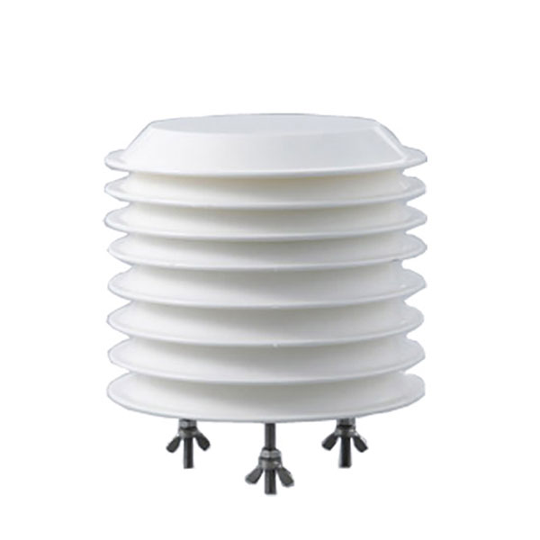 Combined air temperature and relative humidity sensor
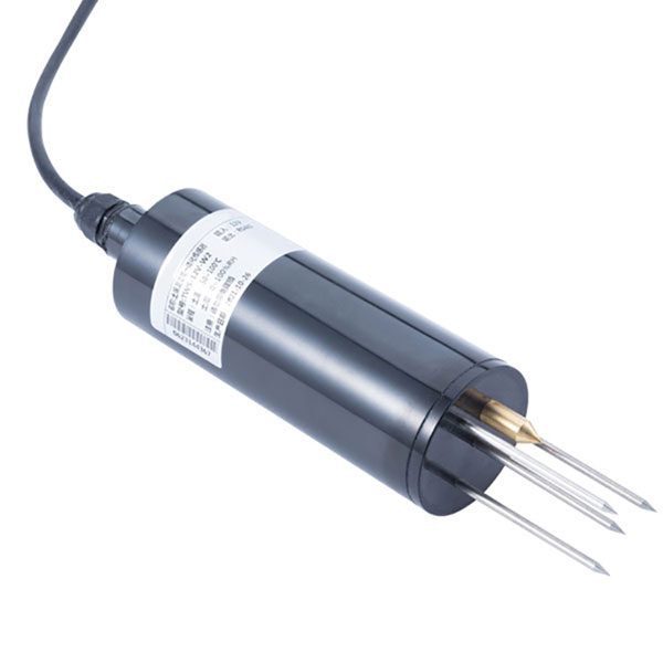 TDR Soil Moisture & Temperature Sensor for irrigation| RS485 |4-20mA| NBL-S-THR
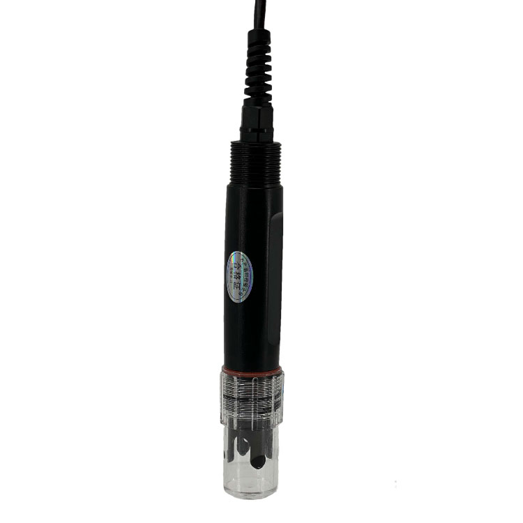 Soil pH sensor RS485 soil Testing instrument soil ph meter for agriculture |NBL-S-PH
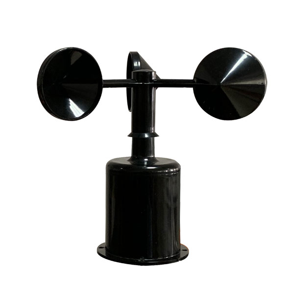 Wind Speed sensor Output Modbus/RS485/Analog/0-5V/4-20mA
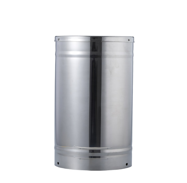 Tipping bucket rain gauge for weather monitoring auto rainfall sensor RS485/Outdoor/stainless steel
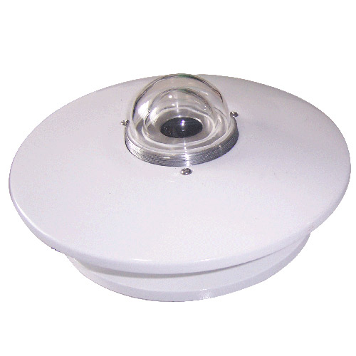 Pyranometer Solar Radiation Sensor 4-20mA/RS485

Screenshot, WhatsApp to identify the QR code
WhatsApp number:+8615367865107
(Click on WhatsApp to copy and add friends)