

— Blogs —
—Products—
 Consumer hotline +8618073152920
 WhatsApp:+8615367865107
Address:Room 102, District D, Houhu Industrial Park, Yuelu District, Changsha City, Hunan Province, China
Product knowledge
Time:2026-09-09 08:00:00 Popularity:191
Treat surface velocity conversion, cross-section survey and datum checks as commissioned model inputs, not hidden factory constants.
| Decision field | Engineering requirement | Evidence for acceptance |
|---|---|---|
| Measurement purpose | State what action radar velocity and flow station should support | Approved monitoring objective |
| Location for radar velocity and flow station | Coordinates, depth or height, orientation and exposure | Drawing and installation photos |
| Data path for radar velocity and flow station | Sensor to logger, controller, gateway and platform | Live measurement with correct unit and timestamp |
| Maintenance for radar velocity and flow station | Safe access and responsible person | Inspection and service record |
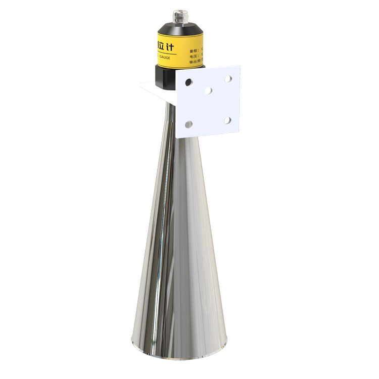
The important limitation is that datum control, channel geometry, dead zone, target angle, sediment, debris, turbulence, condensation and mounting movement can dominate field uncertainty. When radar velocity and flow stations data shifts, compare the field condition with mounting, fouling, configuration and communication records before classifying it as a process event.
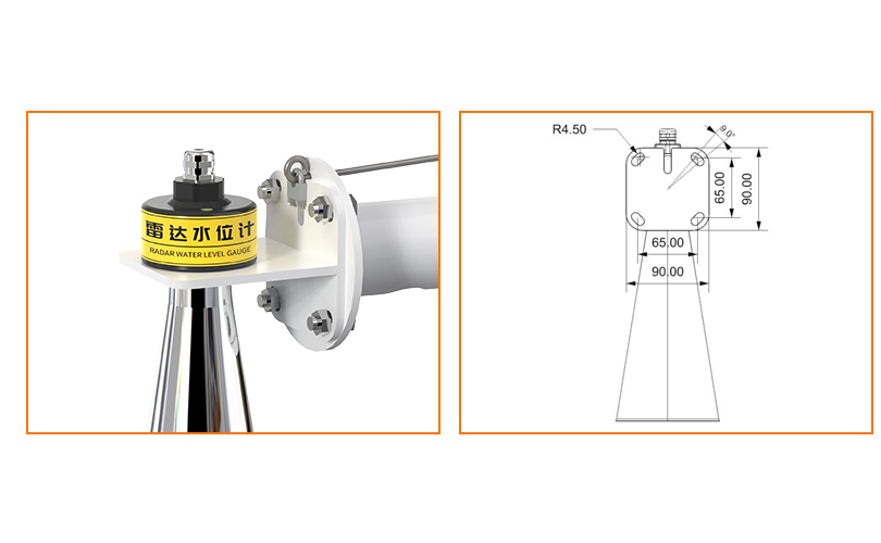
In the system, the level or velocity instrument feeds an RTU or hydrological logger, which combines measurement, timestamps, rainfall and communication for a usable station record. Before approving the Radar Velocity and Flow Station model, trace the measurement point through cable protection, the logger input, communications, the database field and the alarm destination. For radar velocity and flow station, a live number on a display remains only the first check. Across the Radar Velocity and Flow Station measurement chain, preserve engineering units, timestamps, Modbus addresses and device status.
Over the service life of operation, describe radar velocity and flow station as a measuring point with an operating purpose.
For radar velocity and flow station, communication compatibility must be checked at model level. RS485 Modbus RTU is suitable for digital station integration; 4-20 mA may be required in existing control panels, and pulse input is relevant to rainfall channels. RS485 remains only the physical layer; the project record must also state Modbus RTU address, baud rate, parity, stop bits, function code, register address, data type, scaling and engineering unit. On a shared bus serving Radar Velocity and Flow Station, allocate a unique address to every instrument, use a planned trunk, terminate only at the required ends and separate signal wiring from high-current switching conductors.
| RFQ item | Information to provide | Cost or risk controlled |
|---|---|---|
| Application | Purpose and site for radar velocity and flow station | Prevents wrong product family |
| Measurement for radar velocity and flow station | Normal, alarm and peak range; required interval | Avoids under-range or needless overspecification |
| Integration for radar velocity and flow station | PLC/RTU/logger model, signal and protocol | Reduces panel rework |
| Mechanical for radar velocity and flow station | Mounting, depth or height, cable route and material exposure | Defines accessories and serviceability |
| Supply scope for radar velocity and flow station | Sensor only or complete station; documents and spares | Makes prices comparable |
| Commercial for radar velocity and flow station | Quantity, destination, delivery target and packing | Supports a realistic quotation |
| Project role | Decision owned by that role | Deliverable before handover |
|---|---|---|
| Owner or project engineer | Define why radar velocity and flow station is measured and the action threshold | Approved monitoring and acceptance plan |
| Distributor for radar velocity and flow station | Convert the inquiry into a model, accessory and documentation scope | Traceable quotation and current datasheet |
| System integrator for radar velocity and flow station | Confirm power, signal, addresses, scaling and platform tags | Wiring, register mapping and live data test |
| Engineering contractor for radar velocity and flow station | Provide mounting, cable protection, grounding and safe access | As-built drawing and installation photos |
| Operator for radar velocity and flow station | Carry out inspection, cleaning, checks and incident records | Maintenance log and abnormal-data response |
This division matters for radar velocity and flow station because measurement faults often sit between contracts.
Before shipment, bench-test the selected radar velocity and flow station with the intended power supply and host interface where practical. At the measuring location, verify mounting, cable protection, grounding or bonding, address assignment, logger clock, upload interval and alarm destination.
For radar velocity and flow station, do not close acceptance with a screenshot alone. Handover records for Radar Velocity and Flow Station should identify the serial number, installed position, cable and terminal, communication settings, initial comparison, platform tag and routine-inspection owner; include firmware or configuration references where available. Capturing this evidence while commissioning Radar Velocity and Flow Station is far easier than reconstructing it during a fault investigation.
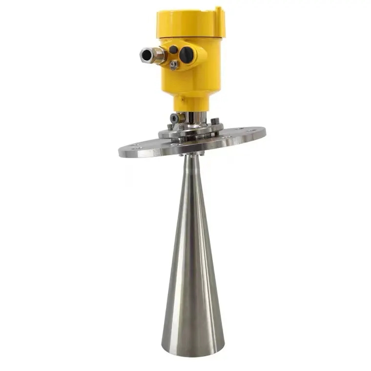
A1: It combines surface velocity, water level and a channel cross-section or rating relationship. The calculation converts measured surface conditions into average velocity and wetted area.
A2: Flow equals average velocity multiplied by wetted area. An outdated or poorly surveyed section can dominate the total error even when sensors operate correctly.
A3: Choose a stable reach with representative flow and a clear beam path. Avoid strong turbulence, backwater, sharp bends, falling water and moving structures where possible.
A4: No. Surface-to-average velocity relationships depend on channel shape, roughness and flow regime. Establish and review coefficients with site observations or reference measurements.
A5: The wetted area and detectable surface motion may become too small for reliable calculation. Define the minimum operating level and how the platform flags out-of-range data.
A6: RS485 is common between instruments and the logger, while 4G or Ethernet can upload station data. Confirm registers, units, timestamps and local storage.
A7: Verify mounting geometry, level reference, cross-section data, raw velocity, calculated flow and comparison with a suitable field method under representative conditions.
A8: Sediment, vegetation, erosion, construction or sensor relocation can change the section or velocity relationship. Re-survey and update the model when those changes are material.
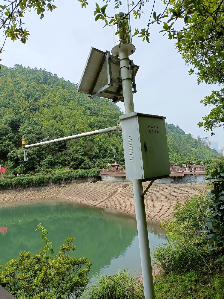
The selected Radar Velocity and Flow Station must combine representative velocity, reliable water level and a defensible channel model. Flow accuracy depends on all three, not only the velocity sensor specification.
Prev:Radar Flow Meter Principle and Application in Open Channels
Next:Radar Water Level Sensor Installation: Datum, Angle and Dead-Zone Checks
Related recommendations
Sensors & Weather Stations Catalog
 Agriculture Sensors and Weather Stations Catalog-NiuBoL.pdf
Weather Stations Catalog-NiuBoL.pdf
Agriculture Sensors Catalog-NiuBoL.pdf
Water Quality Sensor Catalog-NiuBoL.pdf
Related products
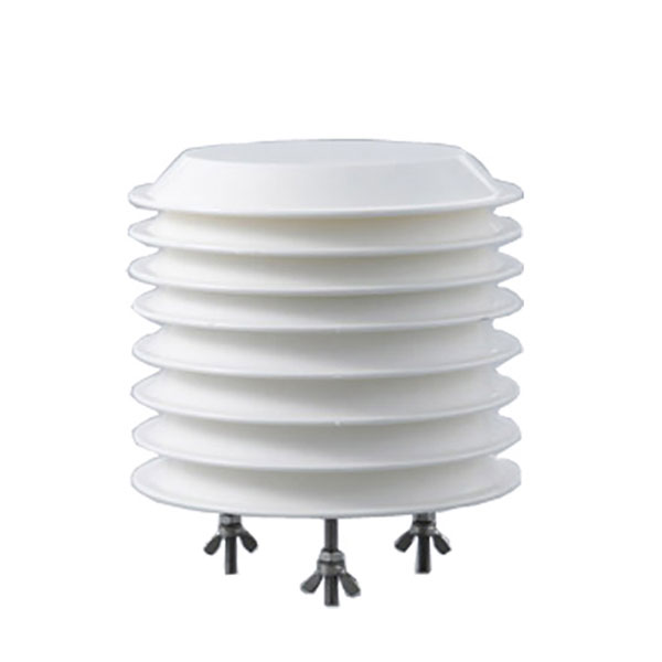 Combined air temperature and relative humidity sensor
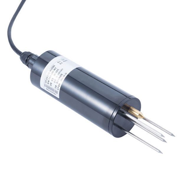 TDR Soil Moisture & Temperature Sensor for irrigation| RS485 |4-20mA| NBL-S-THR
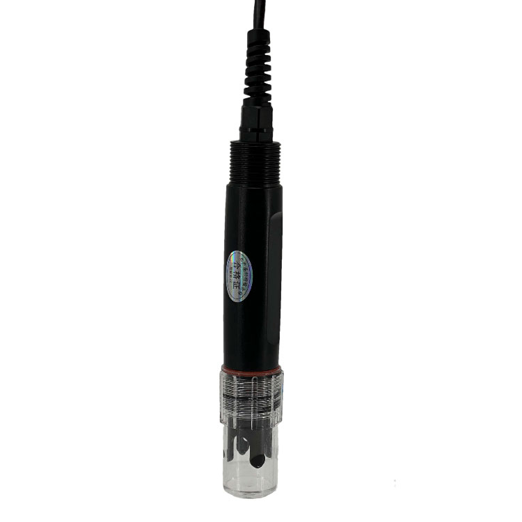 Soil pH sensor RS485 soil Testing instrument soil ph meter for agriculture |NBL-S-PH
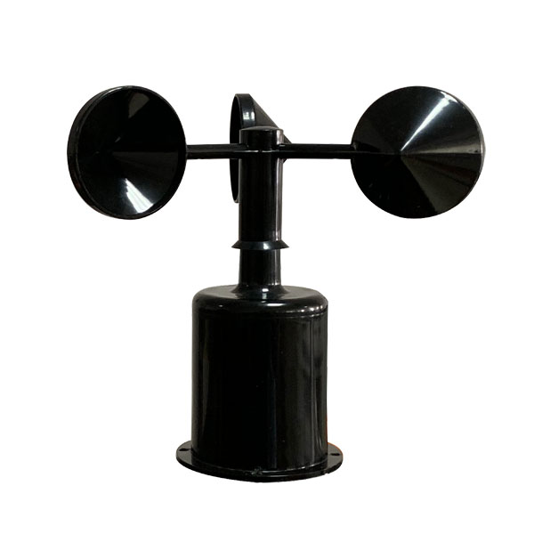 Wind Speed sensor Output Modbus/RS485/Analog/0-5V/4-20mA
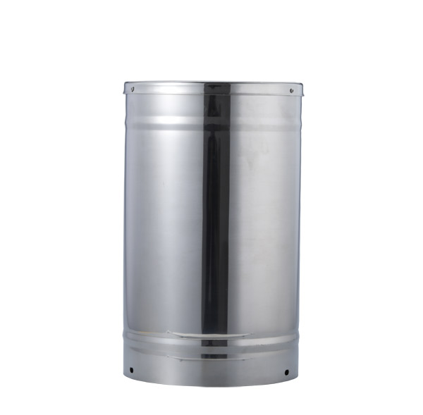 Tipping bucket rain gauge for weather monitoring auto rainfall sensor RS485/Outdoor/stainless steel
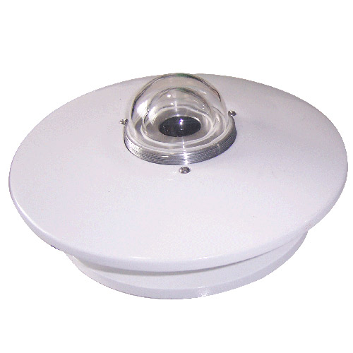 Pyranometer Solar Radiation Sensor 4-20mA/RS485

Screenshot, WhatsApp to identify the QR code
WhatsApp number:+8615367865107
(Click on WhatsApp to copy and add friends)