





— Blogs —
—Products—
 Consumer hotline +8618073152920
WhatsApp:+8615367865107
Address:Room 102, District D, Houhu Industrial Park, Yuelu District, Changsha City, Hunan Province, China
Product knowledge
Time:2026-09-07 16:27:28 Popularity:353
Quick Answer: An RS485 Modbus RTU connection combines an electrical interface (RS485) with a serial communication protocol (Modbus RTU). The device address identifies the responding instrument, the function code selects an operation, and the register address identifies the data. CRC checks the RTU frame for transmission errors. A successful reply still needs the correct data type, scaling and register interpretation before it becomes a valid engineering value.
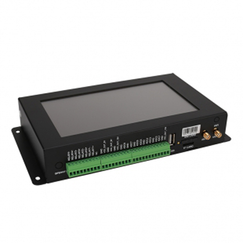
Many sensor integration problems begin when RS485, Modbus RTU and the register map are treated as the same thing. A compatible RS485 port provides the physical connection. The host must also perform the supported Modbus operation and interpret the selected sensor's data correctly.
| Item | Its role | What it does not establish |
|---|---|---|
| RS485 | Differential electrical communication over the serial link | The sensor protocol, parameter locations or engineering units |
| Modbus RTU | Serial message format and communication behavior | A common measurement register map for all manufacturers or models |
| Device address, often called Slave ID | Identifies an instrument on the shared RTU link | The location of a measurement inside that instrument |
| Function code | Selects the operation, such as reading a supported register area | Permission to use every function on every sensor |
| Register address | Identifies the requested data location | The unit, scale or interpretation without the model's register definition |
| CRC | Checks RTU frame integrity | Whether the selected register is the intended measurement or the sensor is calibrated |
A PLC, RTU or data logger therefore needs more than a statement that the sensor "has RS485." Confirm Modbus RTU client/master capability, serial settings and access to the required function and data type. A gateway supporting a different serial protocol will not become compatible merely because its terminals are also marked A and B.
Keep those stages visible during commissioning. A valid response shows that communication is working for that exchange, but it does not prove that the decoded value is correct. A plausible-looking temperature or humidity value can still come from the wrong register or a wrongly interpreted integer.
A read-holding-registers request uses function 03 when the device supports that function for the intended data. Its principal fields are shown below. The register and quantity values are examples of field meaning, not a command guaranteed to work with a particular NiuBoL sensor.
| Field | Example | Interpretation |
|---|---|---|
| Device address | 01 | Query the device configured at address 1 |
| Function | 03 | Read holding registers, if supported for this data |
| Starting address | 00 00 | Protocol starting address zero |
| Register quantity | 00 02 | Request two 16-bit registers |
| CRC | Calculated low byte, then high byte | Calculated over the preceding frame bytes, not over the appended CRC itself |
If any request field changes, calculate the CRC again. A command captured from another sensor cannot be reused safely by editing only the displayed address or register number. During initial read-only testing, avoid write functions that alter calibration or communication settings.
A document may label the first holding register 40001 while the protocol uses a starting address of 0x0000. Another software tool may ask for a zero-based offset, a one-based number or the displayed reference. Confirm what the software expects; do not type 40001 into every address field automatically.
Compare the first known measurement with a checked local value and inspect the raw response. If shifting the starting address makes the result appear plausible, verify the complete map before accepting it. A one-register error can affect every later channel, not just the first one.
| Data definition | Example of correct interpretation | Typical error |
|---|---|---|
| Scaled integer | If the defined divisor is 100, raw 2534 means 25.34 in the specified unit | Applying a divisor copied from another model |
| Signed 16-bit integer | If signed two's-complement is specified, 0xFF9C represents -100 before scaling | Reading it as unsigned 65436 |
| 32-bit value | Read the required two registers and apply the specified integer or floating-point format | Reading one register or using the wrong word order |
| Separate decimal-place field | Use the model's defined concentration and decimal-place registers together | Treating the decimal field as a second measurement |
Standard Modbus register handling does not provide a universal 32-bit sensor data layout. Check the delivered model's word order, signedness, unit and scale. Also distinguish the byte order of data inside a register from the low-byte-first transmission of the RTU CRC.
This matters when a controller is reused for a replacement sensor. An unchanged RS485 connection and the same device address do not establish that the old register map remains valid. Read and compare the required channels again before enabling alarms or control.
| Observed problem | Useful next check |
|---|---|
| No response from a single sensor | Check supply, electrical connection, interface settings and the configured device address before changing data scaling |
| One device works alone but the bus fails when others connect | Check duplicate addresses, wiring topology, termination and the electrical loading of the installation |
| Replies have CRC errors | Check serial settings, noise, wiring and response collisions; verify frame handling in the host |
| A valid Modbus exception is returned | Check the exception code, supported function, register and quantity; this is not the same as no electrical response |
| Valid response, implausible measurement | Check register offset, quantity, signedness, scale and multi-register format |
| Host reads the old address after a change | Update the polling configuration and CRC; verify whether a restart is required for that specific device |
Start with one sensor and one host. A USB-RS485 converter and a suitable Modbus test tool can help verify the raw response before the sensor is connected through a PLC and then a remote platform. Once the local exchange is correct, add the gateway and confirm that the same unit and value reach the final data point.
RS485 A/B labels and reference arrangements must follow the actual devices' wiring definitions. Power down before changing connections and keep the power conductors separate from the communication pair. On a shared bus, configure unique addresses and use an appropriate bus layout and termination arrangement rather than adding branches without checking the interface requirements.
NiuBoL soil, meteorological and water-quality models include RS485 Modbus RTU configurations. Obtain the exact model and version's register definition rather than borrowing one from another product family. A soil moisture value, an ultrasonic weather channel and a salinity reading need different interpretation even when the physical link is similar.
For a replacement or integration inquiry, send the sensor identification, host model, serial settings, intended channels and a raw request/response capture if available. Remove unrelated credentials or network access details. A useful support case states whether the failure is no reply, a CRC error, an exception or an incorrectly decoded value; those observations lead to different checks.
The Modbus Organization's serial-line and application protocol specifications define protocol behavior, while the sensor's register definition supplies the measurement mapping. Both are needed. A generic protocol document cannot tell the PLC which register a particular NiuBoL model uses for salinity.
No. RS485 defines the electrical interface. Modbus RTU defines a serial protocol that can use that interface. Confirm both the interface and the protocol before connecting instruments.
In this Modbus RTU context, those labels normally identify the addressed device. They are different from a register address, which identifies data within that device. Each device polled on the same bus needs an appropriate unique address.
The RTU CRC depends on the preceding message bytes. Changing the device address, function, starting register or quantity can change it. Reusing an old CRC after editing the request can cause the device to reject the frame.
No. The PLC needs the supported Modbus RTU host function and correctly configured communication and data interpretation. Check the model's function codes, register map, data types and scaling, not just the connector.
No. It validates frame integrity for the exchange. The host can still read the wrong register or misinterpret the returned data, and the sensor can still require cleaning or calibration. Communication validation and measurement verification are separate checks.
Do not assume so. The gateway must be configured for the model's actual data definition or use a verified driver. Confirm the local sensor value, gateway value and final platform value before enabling operational alarms.
Commission an RS485 Modbus RTU sensor in layers: verify the electrical link, obtain a valid exchange, confirm the requested registers and decode the engineering value. Preserve the tested serial settings and channel mapping for that model. This makes later replacement and fault investigation more reliable than copying an unverified command between sensors.
Prev:Mining Wastewater Monitoring: pH, Turbidity and Conductivity for Runoff Control
Next:RS485, 4-20mA or 0-5V: How to Choose a Sensor Output Signal
Related recommendations
Sensors & Weather Stations Catalog
 Agriculture Sensors and Weather Stations Catalog-NiuBoL.pdf
Weather Stations Catalog-NiuBoL.pdf
Agriculture Sensors Catalog-NiuBoL.pdf
Water Quality Sensor Catalog-NiuBoL.pdf
Related products
 Combined air temperature and relative humidity sensor
 TDR Soil Moisture & Temperature Sensor for irrigation| RS485 |4-20mA| NBL-S-THR
 Soil pH sensor RS485 soil Testing instrument soil ph meter for agriculture |NBL-S-PH
 Wind Speed sensor Output Modbus/RS485/Analog/0-5V/4-20mA
 Tipping bucket rain gauge for weather monitoring auto rainfall sensor RS485/Outdoor/stainless steel
 Pyranometer Solar Radiation Sensor 4-20mA/RS485


Screenshot, WhatsApp to identify the QR code
WhatsApp number:+8615367865107
(Click on WhatsApp to copy and add friends)

