





— Blogs —
—Products—
 Consumer hotline +8618073152920
WhatsApp:+8615367865107
Address:Room 102, District D, Houhu Industrial Park, Yuelu District, Changsha City, Hunan Province, China
Product knowledge
Time:2026-09-07 16:27:28 Popularity:294
The same temperature, humidity or pressure sensor can have different output forms, but they are oriented to completely different systems. If you select the wrong output mode, you may not be able to connect to the existing controller even if the sensor itself is normal at a later stage.
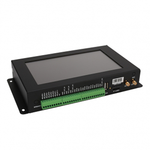
For RS485, 4-20mA or 0-5V: How to Choose a Sensor Output Signal - RS485: for multi-parameter, long-range and digital systems, rS485 adopts differential communication and strong anti-interference ability, which is suitable for long-distance wiring and multi-device bus. With Modbus RTU, an interface can poll multiple sensors by address and read digital quantities directly. It fits PLC, RTU, edge gateways, agricultural IoT and automated weather stations.
For sensor-system integration - RS485: for multi-parameter, long-range and digital systems, 4-20mA is a current signal without Modbus registers. After the collector reads the current, it is converted linearly according to the range. 4mA usually represents the lower limit of the range, and 20mA represents the upper limit of the range. Current loops are very common in industrial sites. The advantages are simple lines, good anti-interference ability, and "less than 4mA" itself can be a break or fault diagnosis clue.
For sensor-system integration - RS485: for multi-parameter, long-range and digital systems, 0-5V is a voltage analog. The controller must have a corresponding voltage input channel and be scaled according to the range. For long-distance wiring, voltage drop, ground potential difference, and electromagnetic interference generally have a more pronounced effect on voltage signals than current loops, and are therefore more suitable for systems with shorter distances and cleaner environments.
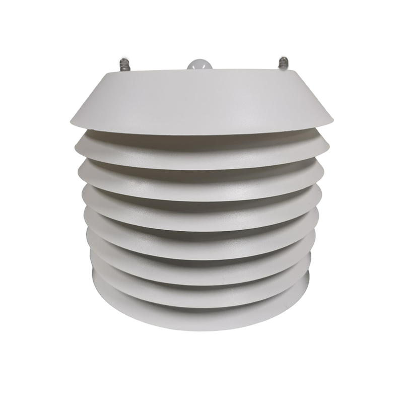
For sensor-system integration - RS485: for multi-parameter, long-range and digital systems, when RS485 has no response, first measure the actual power supply voltage at the sensor end, and then check the power-supply polarity, A/B, serial port driver, COM port, baud rate, and device address. If the same power supply, the same converter, and the same command can normally read other sensors of the same model, and the target device does not even respond to the address, the possibility of hardware or cable failure will increase significantly.
For sensor-system integration - RS485: for multi-parameter, long-range and digital systems, this indicates that the communication link has been established. Next look at the measurement conditions: whether the rain gauge is tipped, whether the soil probe is in contact with the medium, whether the EC is in an air/low conductive environment, whether the wind speed sensor has a stable air source. Also make sure you are reading the correct registers.
For sensor-system integration - RS485: for multi-parameter, long-range and digital systems, let's look at the original register first. Multi-parameter devices often have problems such as "illuminance 200,000, CO ₂ sequence reversal" due to channel sequence, magnification, or decimal point configuration errors. If the original data is normal and the platform is abnormal, the parsing should be corrected instead of replacing the sensor.
For sensor-system integration - RS485: for multi-parameter, long-range and digital systems, connect the multimeter in series to the current loop measurement output. During a normal in-range measurement, a standard 4-20 mA output should not remain below 4 mA; consult the device specification for any configured fault current. If the multimeter has normal current and the RTU reading is abnormal, focus on checking the RTU analog input mode, common ground and range settings; if the multimeter also has no current, check the power supply, wiring and sensors.
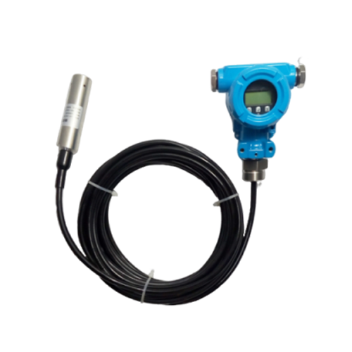
For sensor-system integration - RS485: for multi-parameter, long-range and digital systems, a1: A sensor with 4-20mA output does not output Modbus RTU data by itself. If the system requires Modbus, the conversion can be done by the acquisition module with analog inputs and Modbus outputs.
For sensor-system integration - RS485: for multi-parameter, long-range and digital systems, a2: Because each parameter usually corresponds to an independent current output channel. For example, three analog inputs may be required for three parameters: temperature, humidity, and air pressure.
For sensor-system integration - RS485: for multi-parameter, long-range and digital systems, a3: Accuracy depends first and foremost on the sensing element and the transmitting circuit. The digital transmission avoids the secondary conversion error of the analog quantity on the line, but it cannot simply equate the interface type with the sensor body accuracy.
For sensor-system integration - RS485: for multi-parameter, long-range and digital systems, a4: Measure voltage at the sensor terminals under load, confirm polarity and A/B wiring, then verify baud rate, parity and device address with a direct serial test.
For sensor-system integration - RS485: for multi-parameter, long-range and digital systems, a5: Measure the loop current with a calibrated meter. A normal current with an incorrect controller value indicates an input-mode, scaling or grounding problem downstream of the sensor.
For sensor-system integration - RS485: for multi-parameter, long-range and digital systems, a6: Replace it only after power, wiring, direct output and protocol checks show that the sensor itself cannot produce a valid response under known conditions.
For sensor-system integration - RS485: for multi-parameter, long-range and digital systems, a7: There is usually still a legitimate response during normal communication, but the rainfall value is 0. No return at all is more like a communication, power, or address issue.
For sensor-system integration - RS485: for multi-parameter, long-range and digital systems, a8: If the data comes directly from the tip count and is stepped by 0.2mm, the cumulative value should be an integer multiple of 0.2mm. Data that does not conform to the step should be checked for resolution and magnification.
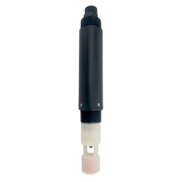
Choose the output signal from the receiving system, cable route, device count and diagnostic requirements, not from the sensor name alone. Confirm channel type and scaling for analog loops, or the complete register map and serial settings for RS485 Modbus RTU, then bench-test one end-to-end channel before duplicating the design across the project.
Prev:RS485 Modbus RTU Sensor Communication: Addresses, Registers and CRC
Next:What Is a Soil Moisture Sensor? VWC, FDR, TDR and RH Explained
Related recommendations
Sensors & Weather Stations Catalog
 Agriculture Sensors and Weather Stations Catalog-NiuBoL.pdf
Weather Stations Catalog-NiuBoL.pdf
Agriculture Sensors Catalog-NiuBoL.pdf
Water Quality Sensor Catalog-NiuBoL.pdf
Related products
 Combined air temperature and relative humidity sensor
 TDR Soil Moisture & Temperature Sensor for irrigation| RS485 |4-20mA| NBL-S-THR
 Soil pH sensor RS485 soil Testing instrument soil ph meter for agriculture |NBL-S-PH
 Wind Speed sensor Output Modbus/RS485/Analog/0-5V/4-20mA
 Tipping bucket rain gauge for weather monitoring auto rainfall sensor RS485/Outdoor/stainless steel
 Pyranometer Solar Radiation Sensor 4-20mA/RS485


Screenshot, WhatsApp to identify the QR code
WhatsApp number:+8615367865107
(Click on WhatsApp to copy and add friends)

