





— Blogs —
—Products—
 Consumer hotline +8618073152920
WhatsApp:+8615367865107
Address:Room 102, District D, Houhu Industrial Park, Yuelu District, Changsha City, Hunan Province, China
Product knowledge
Time:2021-12-05 19:48:55 Popularity:2219
Quick Answer: Surge protection and optical isolation solve different electrical problems. A surge protective device limits transient voltage and diverts surge current through a designed path. Optical isolation transfers a signal across an electrically separating barrier. One does not replace the other: an outdoor sensor link may need both, together with suitable bonding, routing and power protection.

An optocoupler uses light to transfer information between an input circuit and an output circuit. The signal can cross without a direct conductive signal connection. In an industrial installation, that separation can help keep a difference in local ground potential from becoming an unwanted current path through the communications electronics.
Galvanic isolation is the broader function; optical coupling is one way to implement it. Capacitive or magnetic methods can also provide an isolation barrier. The important questions are which circuits are separated, how the isolated side receives power and whether the complete assembly meets the required electrical ratings.
An optocoupler symbol alone does not prove that the complete circuit is isolated. If both sides connect to the same SGND net, that shared connection prevents galvanic separation between the sides. Check the actual net connections and power arrangement, not only the presence of an optical component.
These distinctions matter because RS485 is differential but not unlimited in common-mode tolerance. Isolation can address ground-potential differences, provided the signal and power arrangement preserve the intended barrier. Differential signaling by itself does not prove that two remote ground systems can be connected under any conditions.
A signal-line surge protector acts on excessive transient voltage at its terminals. It does not create the same function as an optocoupler. Its protective behavior depends on the connected conductors, protection modes and the path provided for surge current. A nominally suitable component can perform poorly if the installation creates an unsuitable return path.
IEC 61643-21:2025 covers surge protective devices for telecommunications and signalling networks. Its scope includes voltage limitation and surge-current diversion. Referencing that standard does not certify a particular sensor, router or assembled cabinet; compliance needs evidence for the actual device and applicable tests.
| Function | What it addresses | What it does not establish |
|---|---|---|
| Signal-line surge protection | Transient voltage entering on measurement or communication conductors | Galvanic separation or protection of other entry paths |
| Optical isolation | Signal transfer across an electrical barrier | Unlimited surge-energy handling or a complete lightning design |
| Isolated power | Power transfer while maintaining specified separation | Suitability of the signal interface or protection of all external wiring |
| Bonding and routing | Controlled electrical relationships and current paths at the installation | A universal replacement for interface-specific protective devices |
Why use both surge protection and optical isolation? A long outdoor cable can expose the equipment to transient energy while also connecting locations with different ground potentials. The two protective functions address different parts of that problem. Their ratings and physical arrangement must be coordinated rather than selected as unrelated accessories.
An isolation withstand test voltage is not a permitted continuous working voltage. A surge-current rating is not the current a signal circuit may carry in normal service. A component-level ESD rating is not proof that a complete weather station will survive a lightning event. Keep the test condition, waveform and equipment level attached to every number used in a comparison.
| Parameter to compare | Units or description | Why it matters |
|---|---|---|
| Normal circuit voltage | VDC or VAC, including normal tolerances | Protection must not operate during valid service. |
| Protective voltage behavior | Limiting voltage at stated test conditions | The remaining transient must be assessed against the protected input. |
| Surge-current capability | A or kA with test waveform and duty | A headline current without conditions is not a sufficient comparison. |
| Signal loading | Capacitance, resistance, bandwidth or supported data rate | The protective device must not prevent correct communication or measurement. |
| Isolation barrier | Working voltage and withstand test, with duration and insulation category | Separate continuous service limits from short-duration testing. |
| Installation limits | Temperature, enclosure rating, terminals and conductor requirements | A panel component may need additional outdoor protection. |
There is no single correct protection voltage or kA rating for every NiuBoL sensor network. Select for the actual interface, cable exposure, equipment withstand and site electrical design. Quoting a large rating on an unrelated power protector does not demonstrate that it is suitable for a low-voltage RS485 input.
An RS485 cable carries differential data between A and B, with reference and shielding arrangements determined by the equipment design. A suitable protector must account for the actual conductors and modes of exposure. A power-supply protector cannot be assumed suitable merely because it has enough terminals.
For industrial RS485 integration, check normal signal levels, data rate, added capacitance, series resistance and whether protection changes the termination arrangement. Then test communication with the protector installed. A device that passes slow bench messages may still need evaluation at the installed bus length and polling conditions.
Isolation also needs a power-path review. If an external wire or accessory recreates a conductive connection across the intended barrier, the arrangement may no longer provide the separation expected. Check the complete connected assembly, including service connections, rather than judging only the isolated signal component.
Modbus RTU does not specify the lightning protection of a product. It describes communication behavior. Likewise, an isolated interface does not automatically change a private sensor protocol into Modbus RTU, extend addressing capacity or correct an incorrect register map.

A protected power input does not remove exposure through a sensor cable, Ethernet connection or external antenna. Draw the actual entry paths before choosing components. At a solar-powered station, include the panel and battery wiring as well as the sensor and communications connections; absence of mains power does not remove outdoor electrical exposure.
Cabinet entry is a useful place to organize protection and bonding, but placement must follow the site design. Keep connection paths short and direct as specified by the selected protective devices. Avoid loops or a layout that runs protected wiring beside incoming exposed wiring and couples a transient back into the equipment side.
A surge protector needs a low-impedance path appropriate to the protection design. Long, looped earth conductors reduce performance during a fast transient. Bonding, enclosure grounding and cable-screen treatment should follow the site electrical plan rather than be decided one device at a time.
Do not remove protective earth to eliminate a communication fault. Have qualified personnel distinguish signal-reference problems from protective-bonding requirements.
A 4-20 mA loop, an RS485 link and a dry-contact rain-gauge circuit have different normal behavior. Check loop supply and burden for a current channel. For pulse counting, check input thresholds and whether added components alter pulse edges or introduce missed counts. For serial data, check frame errors and timeouts with all installed protection in place.
These checks are especially relevant when a station combines instruments from different sources. Cable colors and connector positions are not a universal interface standard. Identify each conductor from the actual equipment connection requirements before applying a common cabinet wiring scheme.
Failures associated with nearby thunderstorms justify reviewing outdoor entry paths and surge coordination. Communication errors that follow a motor start may instead involve interference, grounding, supply disturbance or routing. A recurring error is evidence to investigate, not proof that an isolator or a larger surge protector will solve it.
Begin with the event timing and affected channels. Did the entire logger restart, did one serial device stop responding, or did the displayed measurement become noisy? Compare supply condition, device status and communication logs. Inspect for water entry, damaged cable and loose terminals before attributing every interruption to lightning.
Do not repeatedly reset a failed protector or bypass it to keep a station online without understanding its status and replacement requirements. Isolation and protective equipment can fail without an obvious external burn mark. Use the manufacturer's inspection method and involve qualified electrical personnel where damage or unsafe conditions are suspected.
After safe installation, check conductor identification, polarity, terminal security and the specified bonding arrangement. Restore power under the approved procedure, then verify a known input, normal data exchange and the behavior of an unavailable sensor. For analog channels, compare readings before and after the added interface to identify loading or scaling errors.
A successful Modbus read proves communication at that moment; it does not prove surge withstand. Conversely, a correctly selected protector does not prove that the sensor was calibrated or the gateway mapping was correct. Keep functional checks separate from the protective-device documentation and any required installation tests.
Do not apply an insulation-resistance or high-voltage test to connected electronics unless the equipment procedure explicitly permits it. Panel test arrangements may require devices to be disconnected or handled differently. Improvised testing can damage the parts the design is intended to protect.
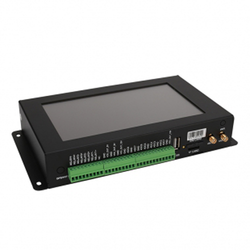
For a NiuBoL monitoring installation, provide the sensor outputs, supply arrangement, cable routes and lengths, cabinet location and any existing isolation or protection details. This allows the equipment interfaces to be coordinated with the site electrical designer. A data logger's connector layout alone cannot establish the protection required.
It must not be treated as a complete direct-strike protection system. Its barrier has defined electrical limits. Site lightning protection, bonding, routing and coordinated surge protection require a separate design.
No. Check the signal barrier, power supply and every external conductive connection. A shared connection can defeat the intended separation even when the signal path includes an optocoupler.
Only if it is specifically suitable for that signal application. Normal voltage, loading, protection modes and data behavior must match. A mains-rated protector is not a generic substitute for a signal-line device.
No. Enclosure protection concerns environmental entry; galvanic isolation concerns electrical separation. An outdoor enclosure and the equipment inside it need their own appropriate specifications.
No. Isolation does not establish supported function codes, addresses or data formats. Resolve electrical faults and protocol mapping as separate tasks.
Compare equivalent protected circuits, interfaces and installation scope. Include suitable enclosure mounting, wiring, bonding, documentation and replaceable parts. A component price without its application conditions is not a complete protection proposal.
Keep the installed device references, connection arrangement, status-indicator meaning and replacement procedure. Record surge-related events and changed modules so a later failure can be traced to the actual installation.
Surge protection and optical isolation are complementary functions, not interchangeable labels. Protect the actual signal and power paths, maintain the intended isolation barrier, and verify that the completed installation still measures and communicates correctly. Electrical protection must be coordinated with the site's bonding and safety design.
Related recommendations
Sensors & Weather Stations Catalog
 Agriculture Sensors and Weather Stations Catalog-NiuBoL.pdf
Weather Stations Catalog-NiuBoL.pdf
Agriculture Sensors Catalog-NiuBoL.pdf
Water Quality Sensor Catalog-NiuBoL.pdf
Related products
 Combined air temperature and relative humidity sensor
 TDR Soil Moisture & Temperature Sensor for irrigation| RS485 |4-20mA| NBL-S-THR
 Soil pH sensor RS485 soil Testing instrument soil ph meter for agriculture |NBL-S-PH
 Wind Speed sensor Output Modbus/RS485/Analog/0-5V/4-20mA
 Tipping bucket rain gauge for weather monitoring auto rainfall sensor RS485/Outdoor/stainless steel
 Pyranometer Solar Radiation Sensor 4-20mA/RS485


Screenshot, WhatsApp to identify the QR code
WhatsApp number:+8615367865107
(Click on WhatsApp to copy and add friends)

