

— Blogs —
—Products—
 Consumer hotline +8618073152920
WhatsApp:+8615367865107
Address:Room 102, District D, Houhu Industrial Park, Yuelu District, Changsha City, Hunan Province, China
Product knowledge
Time:2025-01-11 17:23:44 Popularity:1710
Doppler flow meter reverse flow requires more than a sensor that displays velocity. Specify a bidirectional configuration, a defined positive direction, signed flow data and the required totalizers. Net volume subtracts reverse transport from forward transport; gross transported volume adds their magnitudes. A gateway or report that discards the sign can turn a useful bidirectional measurement into an incorrect water balance.
Drainage outfalls, tidal channels and pump-station connections can experience periods when water moves opposite to the usual direction. A forward-only total may then answer a different question from the owner's water-balance requirement. Before selecting a meter, decide whether the project needs forward discharge, reverse inflow, net export or the total volume moved in both directions.
An ultrasonic Doppler instrument derives velocity from the frequency shift of sound scattered by moving particles or bubbles. In an area-velocity installation, velocity and water level are used with the channel geometry to calculate discharge. That calculation still needs a representative velocity relationship and the correct wetted area; detecting a direction does not establish the accuracy of the entire discharge measurement.
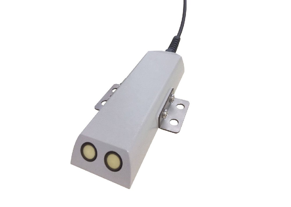
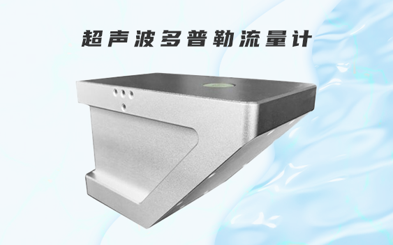
The NiuBoL Doppler velocity meter is offered with unidirectional and bidirectional measurement configurations. Do not infer bidirectional capability from the words ultrasonic or RS485. Request the exact supplied version and its signed velocity, flow and accumulated-volume behavior before using it at a reversing site.
| Selection item | Product specification or configuration | Reverse-flow check |
|---|---|---|
| Velocity configuration | 0.03-5 m/s unidirectional; bidirectional configuration available | Obtain the signed limits for the ordered version; do not transfer the unidirectional range |
| Water level | 0.03-5 m | Check the expected depth in both flow directions and at low water |
| Supply | DC 10-30 V | Verify voltage at the instrument during the measurement cycle |
| Current at 12 V | 65 mA standby; 106 mA during measurement | Include actual duty cycle and the external logger in the power budget |
| Communication | RS485 Modbus RTU | Verify signed format, units, scaling and totalizer registers |
| Sensor housing | ABS; IP68 | Assess submergence, cable condition, debris and sediment at the site |
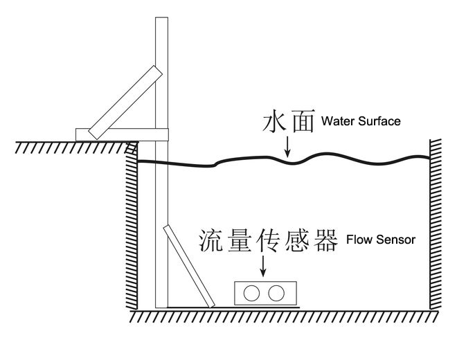
Mounting orientation and positive direction must agree. A label such as positive means downstream is incomplete until downstream is defined at that location. Put the reference direction on the installation drawing and in the logger configuration. Record which physical direction should produce a positive velocity and which should produce a negative one.
Use a signed discharge convention before integrating volume over time. For this explanation, Q is positive in the chosen forward direction. Forward volume is the time integral of positive Q; reverse volume is the magnitude accumulated while Q is negative. Net volume equals forward volume minus reverse volume. Gross transported volume equals forward volume plus reverse volume.
| Quantity | Illustrative value | Question it answers |
|---|---|---|
| Forward volume | 12 m3 | How much passed in the positive direction? |
| Reverse volume, expressed as a magnitude | 3 m3 | How much passed in the opposite direction? |
| Net volume | 12 - 3 = 9 m3 | What was the signed balance across the section? |
| Gross transported volume | 12 + 3 = 15 m3 | How much movement occurred, regardless of direction? |
This is an arithmetic illustration, not a measured project result. If the same water oscillates across a section, gross transport can be large while net export is small. Neither number is inherently wrong, but they must not share an ambiguous label such as total flow. If a contract defines a different totalization convention, implement and label that convention explicitly.
Keep instantaneous discharge and accumulated volume separate as well. Discharge needs a rate unit such as m3/s; volume uses m3. A numerical range presented without a rate unit cannot be adopted as an instantaneous-discharge specification. Resolve the unit and register meaning before mapping the signal into reports.
A signed register interpreted as unsigned can produce a large positive value instead of a negative one. A gateway that applies an absolute-value operation may show plausible speed while removing direction. Check the sensor output, gateway value and stored record against each other. RS485 describes the electrical interface; Modbus RTU does not make every device's register type or scaling identical.
Near slack water, noise and the instrument's low-velocity limit can make the sign unstable or the reading invalid. Do not sum every small sign change as proven physical reversal. Agree how low velocities, signal quality and invalid samples are handled. Any deadband should be justified against the project requirement and must not conceal sustained reverse transport that matters to the water balance.
A bend, outfall structure or nearby pump can create different velocity profiles in forward and reverse flow. A correction established in one direction may not represent the other. Compare discharge with an appropriate independent method under both conditions where practicable. A successful sign test establishes direction handling, not full cross-section measurement accuracy.
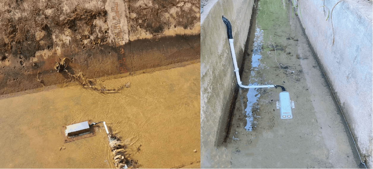
Begin with a static configuration review: physical orientation, reference direction, cross-section dimensions, water-level datum and the exact register definitions. Retain signed velocity and discharge in the logger where available. If forward and reverse totals are calculated outside the meter, document the integration interval, units, handling of missing samples and restart behavior.
Avoid entering a channel or manipulating a live pump system merely to obtain a test direction. Use the site's approved access and operational procedures. Where natural reversal is seasonal, record the limitation and arrange a later field check rather than claiming that a register simulation validates reverse hydraulics.
Doppler sensing needs usable acoustic scatterers and a submerged, unobstructed measurement zone. Very clear water can produce insufficient scattering; heavy sediment, entrained air or debris can also impair measurement. Reverse-flow capability does not solve these problems. Check actual conditions during the events the project needs to measure, not just during a convenient dry-weather inspection.
For a quotation, send the channel shape, normal and minimum depths, expected velocities in both directions, water characteristics and the required reporting quantities. Include the existing PLC or RTU register requirements. NiuBoL can then assess the direction-capable configuration and integration scope without treating every open-channel installation as the same measurement task.
No. Direction capability depends on the instrument configuration and output implementation. Specify a bidirectional version and verify its signed limits and register behavior. A unidirectional range is not evidence of reverse-flow capability.
Use the quantity required by the operational or contractual question. Forward volume describes outward transport, reverse magnitude describes backflow, net volume describes their balance, and gross volume describes total movement. Retaining both directional totals makes later interpretation easier.
Not to obtain a reliable volume when wetted area or the velocity-to-discharge relationship changes. Calculate discharge using the applicable geometry and measurement relationship, then integrate discharge over valid time intervals. Keep missing intervals identifiable.
The flow may be near slack water, below the useful velocity range or affected by weak signal quality. Examine those conditions before interpreting each sign change as a reversal. Define low-flow and invalid-data handling during commissioning.
No. It checks the communications and software path. Field verification is still needed for physical direction, representative velocity and discharge calculation under reverse hydraulic conditions.
Include positive-direction orientation, signed data formats, units, scale factors, totalizer definitions, time basis, reset behavior and treatment of outages. These details prevent different systems from assigning different meanings to the same flow record.
Doppler flow meter reverse flow is a measurement and reporting requirement, not just a sensor option. Choose the appropriate configuration, establish the physical sign convention and retain clearly named directional totals. Verify the signed data path separately from hydraulic accuracy so the resulting water balance remains interpretable.
Prev:Submersible Level Sensor in Closed Tanks: Check Headspace Pressure
Next:Aquaculture Water Quality Monitoring Plan: Routine Sensors and Targeted Tests
Related recommendations
Sensors & Weather Stations Catalog
 Agriculture Sensors and Weather Stations Catalog-NiuBoL.pdf
Weather Stations Catalog-NiuBoL.pdf
Agriculture Sensors Catalog-NiuBoL.pdf
Water Quality Sensor Catalog-NiuBoL.pdf
Related products
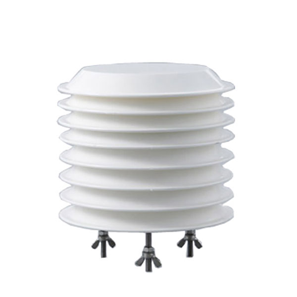 Combined air temperature and relative humidity sensor
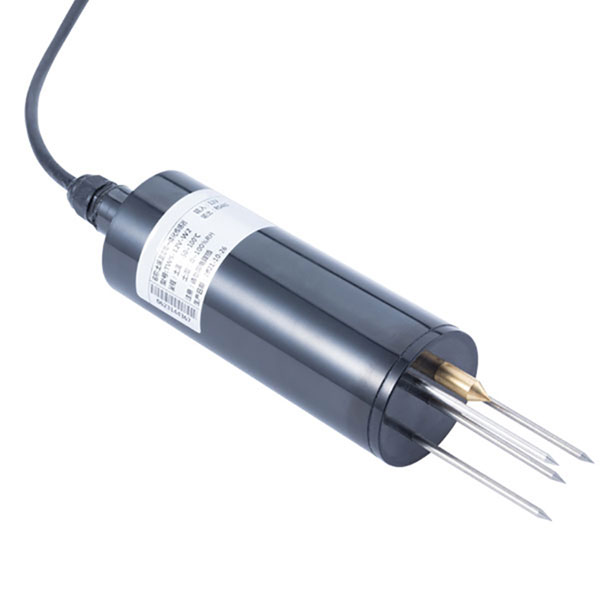 TDR Soil Moisture & Temperature Sensor for irrigation| RS485 |4-20mA| NBL-S-THR
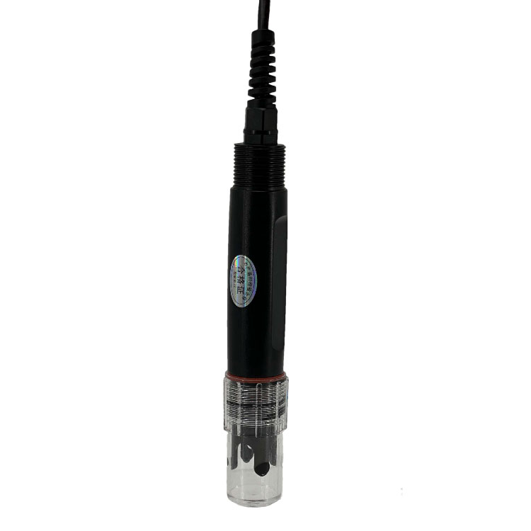 Soil pH sensor RS485 soil Testing instrument soil ph meter for agriculture |NBL-S-PH
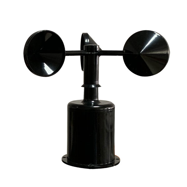 Wind Speed sensor Output Modbus/RS485/Analog/0-5V/4-20mA
 Tipping bucket rain gauge for weather monitoring auto rainfall sensor RS485/Outdoor/stainless steel
 Pyranometer Solar Radiation Sensor 4-20mA/RS485


Screenshot, WhatsApp to identify the QR code
WhatsApp number:+8615367865107
(Click on WhatsApp to copy and add friends)