





— Blogs —
—Products—
 Consumer hotline +8618073152920
WhatsApp:+8615367865107
Address:Room 102, District D, Houhu Industrial Park, Yuelu District, Changsha City, Hunan Province, China
Product knowledge
Time:2025-10-14 14:50:46 Popularity:1254
Quick Answer: Wind speed measures how fast air moves; wind direction identifies where it comes from. A cup anemometer measures speed, while a wind vane measures direction. A two-axis ultrasonic instrument can measure both. For agricultural monitoring, these readings answer different questions: speed describes airflow intensity, and direction identifies the upwind and downwind sectors. Neither reading alone establishes whether a spraying operation is acceptable.
An agricultural weather display showing 3 m/s does not tell an operator which neighboring field is downwind. A display showing east does not reveal whether the flow is weak or strong. A monitoring specification therefore needs two named channels, their units and their averaging periods, rather than an ambiguous request for a wind sensor.
Wind speed is a scalar quantity. Wind direction is an angular bearing, not a separate velocity vector. Together, horizontal speed and direction define horizontal wind velocity. A three-dimensional wind instrument adds the vertical component; a conventional cup-and-vane pair does not measure vertical air motion.
| Measurement | Meaning and units | What it cannot establish alone |
|---|---|---|
| Wind speed | Magnitude of air movement; commonly m/s, km/h or knots | The downwind destination of airborne material |
| Wind direction | Direction of origin; degrees clockwise from north or a compass label | Airflow strength, transport distance or deposition |
| Horizontal wind velocity | Speed and direction combined for a specified time and location | The complete path through changing terrain and atmospheric layers |
Unit conversion matters when a controller and a dashboard use different conventions: 1 m/s equals 3.6 km/h. Convert limits and recorded values consistently; do not compare a numerical limit in km/h against a tag stored in m/s. Also distinguish an instantaneous value, an interval mean and a gust statistic before using them together.
Meteorological wind direction describes the direction of origin. An east wind comes from the east and travels generally toward the west. North is 0 degrees, east 90, south 180 and west 270. North may be represented as 0 or 360 depending on the receiving system. The National Weather Service explanation of wind barbs illustrates how origin and speed are represented together.
For an illustrative farm-map check, assume a measured direction of 160 degrees. Its opposite bearing is 340 degrees: the general downwind sector is north-northwest, not south-southeast. This reversal is important when a map contains a water source or neighboring crop. It is a directional check only, not a prediction of the amount of spray that will reach either location.
A map arrow needs an explicit convention. Some dashboards draw an arrow pointing toward the wind's origin; others draw the direction of travel. During commissioning, select a known bearing and compare the numeric value, compass word and arrow. A plausible-looking arrow can be wrong by 180 degrees while every digital packet is valid.
Low wind speed introduces another limitation. A vane may retain a previous direction or move irregularly when airflow is insufficient to orient it. A returned numeric angle is not proof of a meaningful direction. Configure calm or direction-quality handling in the logger or application; do not assume that every sensor automatically sends an undefined-direction flag.
Wind direction helps locate sensitive downwind areas, while wind speed helps characterize transport conditions. Actual decisions also depend on the product label, application equipment, droplet specification, setbacks, temperature inversions and local requirements. There is no universal safe spraying speed that can be assigned to every farm and chemical.
Very low wind is not automatically safer. It can coincide with variable direction or atmospheric conditions that require a different operational judgment. Use wind observations to support the applicable procedure, not to create a blanket “spraying allowed” output. A station some distance from the work area may also miss local sheltering or terrain-driven flow.
Wind speed is one input to reference evapotranspiration calculations, together with radiation, temperature and humidity. Wind direction is not a direct input to the standard reference calculation. A system should record the wind measurement height and apply the chosen method's height treatment rather than substituting a reading from an arbitrary mounting height.
Additional wind direction data can still help explain why one field edge dries differently from another. That does not turn it into an irrigation volume command. Root-zone water, crop stage, soil properties and irrigation performance determine whether an observed atmospheric demand requires water application.
For a naturally ventilated greenhouse, the windward side changes with direction, while wind speed affects pressure-driven exchange and structural operating limits. The controller also needs vent position, indoor conditions and the greenhouse supplier's operating restrictions. An outdoor weather reading cannot verify that a vent has opened or that crop-zone airflow is adequate.
For exposed crops, wind records help investigate lodging or branch damage, but a recorded mean does not prove the peak load on a plant. Maintain the acquisition interval and gust definition with the record. Pest migration assessments likewise need biological observations and relevant atmospheric transport information; a surface station alone cannot predict an invasion time.
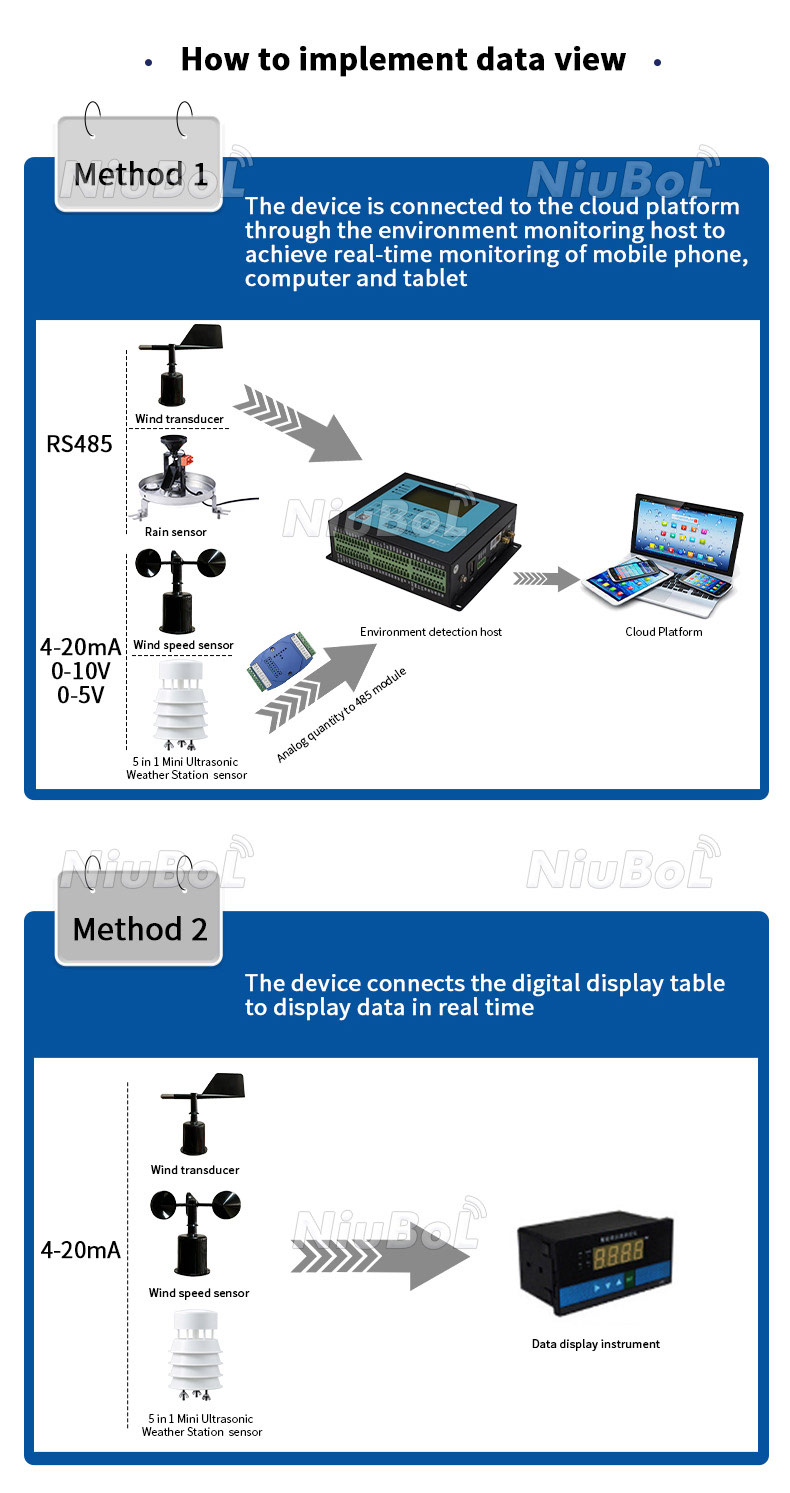
A speed-only instrument is suitable when the receiving process genuinely needs only speed. If a project must identify upwind and downwind sectors, add a direction channel or choose a combined instrument. Separate sensors allow independent replacement and placement; a combined ultrasonic sensor reduces separate mounting points but still needs an unobstructed acoustic path and a correct orientation reference.
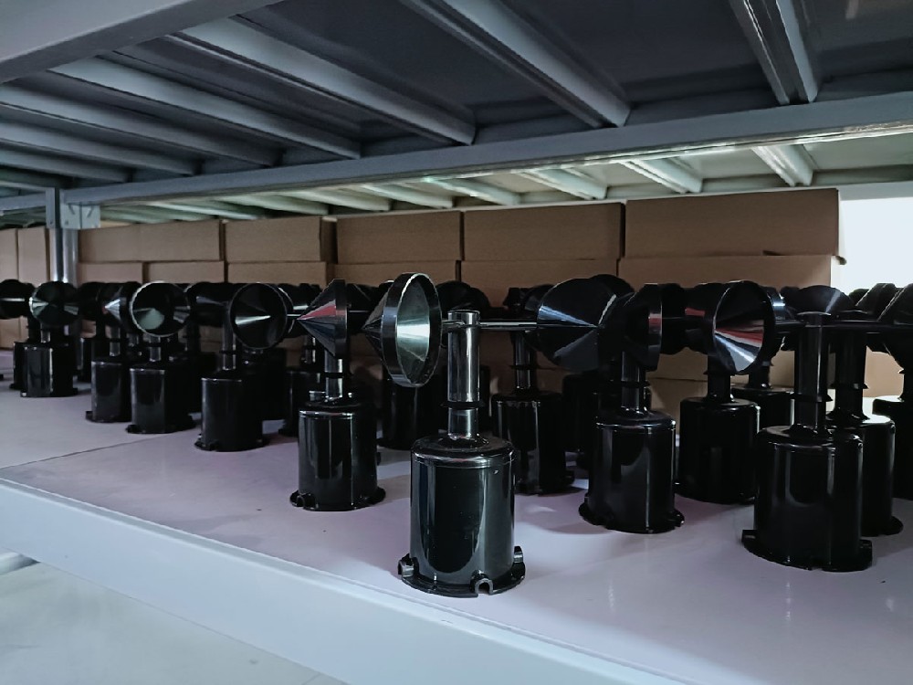
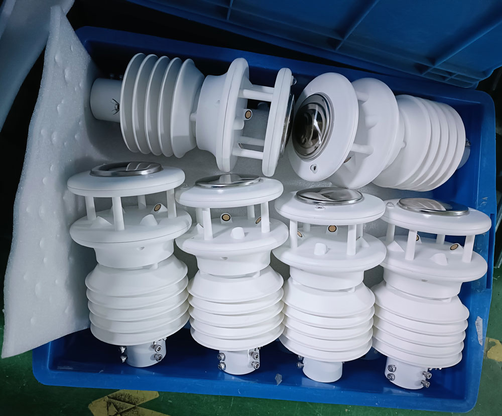
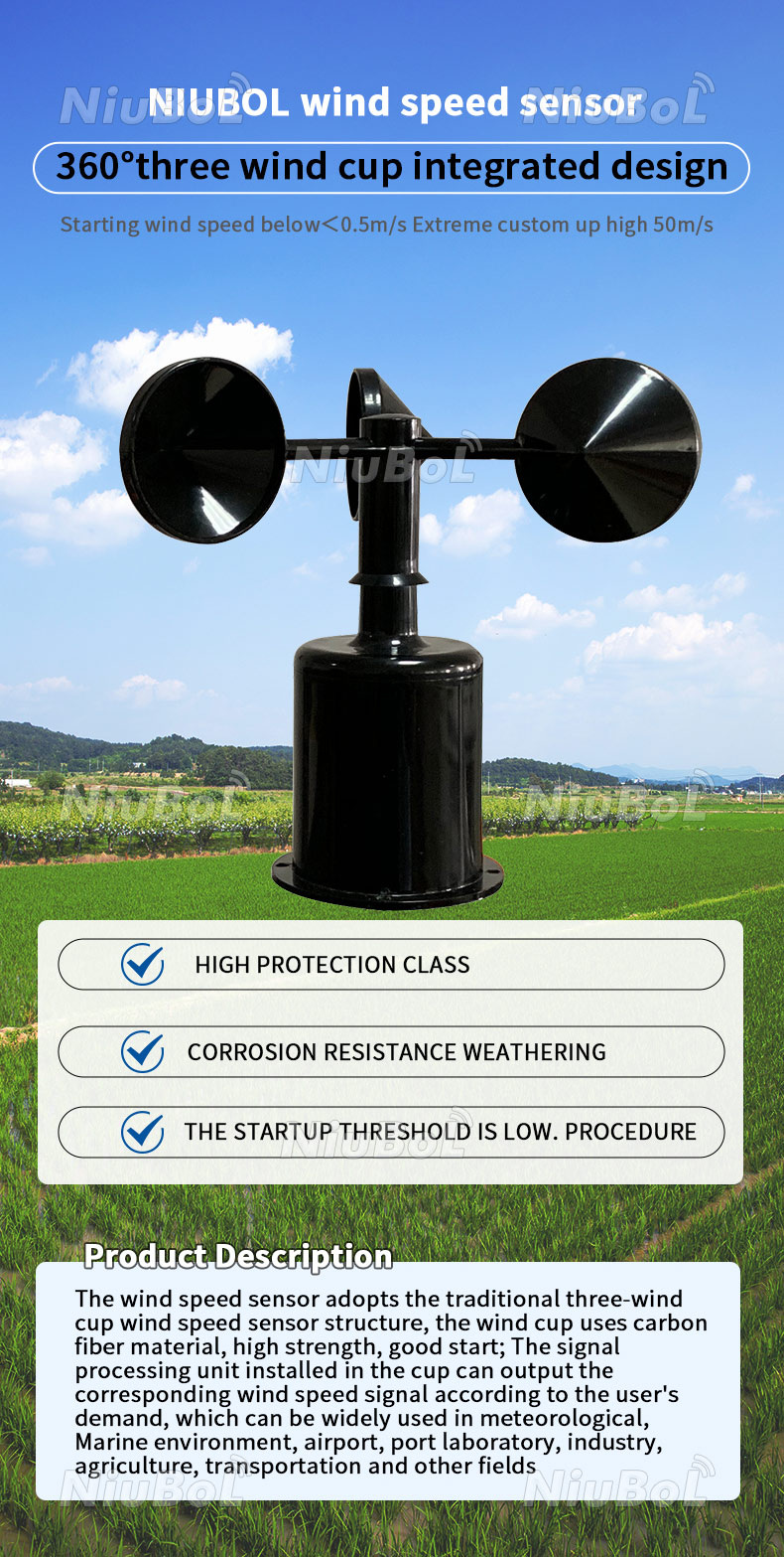
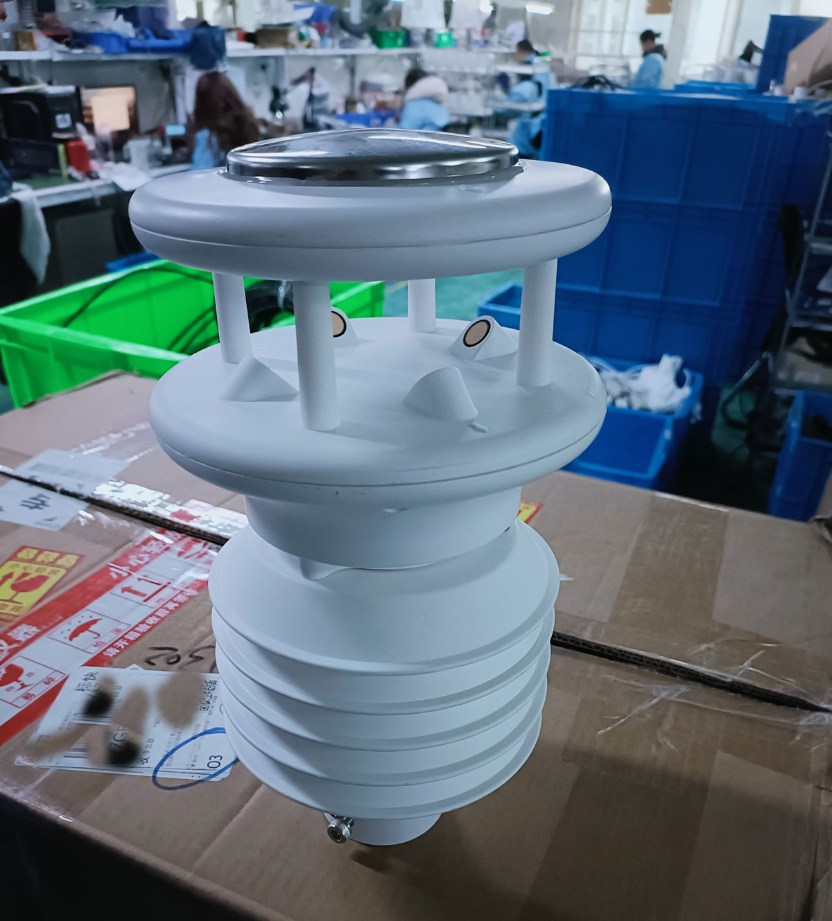
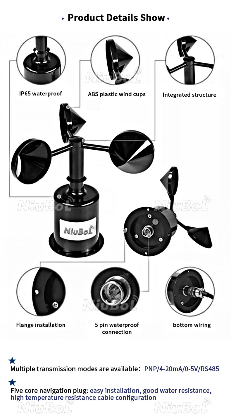
The NiuBoL wind sensor range includes NBL-W-SS cup anemometers, NBL-W-DS wind direction sensors and combined ultrasonic configurations such as NBL-W-21GUWS. Mechanical and ultrasonic designs should be compared using the required low-speed performance, exposure, service access and output, not an assumption that one principle is more accurate in every installation.
| Selection item | NBL-W-SS | NBL-W-DS |
|---|---|---|
| Measured quantity | Wind speed | Wind direction |
| Range | 0-45 or 0-70 m/s, selected version | 0-360 degrees |
| Accuracy | +/-(0.3 + 0.03V) m/s; V is wind speed in m/s | +/-3 degrees |
| Starting wind speed | At most 0.5 m/s | At most 0.5 m/s |
| Supply choices | 5 VDC or 12-24 VDC version | 5 VDC or 12-24 VDC version |
| Output choices | Pulse, 4-20 mA, voltage or RS485 version | 4-20 mA, voltage or RS485 version |
| Power consumption | 50 mW | 0.15 W |
| Operating temperature | -40 to 80 degrees C | -40 to 80 degrees C |
| Ingress protection | IP65 | IP65 |
| Standard cable length | 2.5 m | 2.5 m |
These are separate ordered output and supply choices, not simultaneous ports on every unit. At 10 m/s, the NBL-W-SS accuracy expression evaluates to +/-0.6 m/s. Its 0.1 m/s resolution does not mean +/-0.1 m/s accuracy. Ask for the cable jacket material, connector arrangement and any required extended cable as order-specific details rather than inferring them from IP65.
RS485 is the electrical interface; Modbus RTU defines the message exchange. The RS485 NBL-W-SS and NBL-W-DS versions use 9600 baud, eight data bits and no parity, with the selected stop-bit setting matched at the receiver. Allow at least 1000 ms between communications to an instrument. Set unique device addresses before sharing a bus.
The same raw number has different meanings in these two instruments. A returned hexadecimal value 00 B4 is decimal 180. In the NBL-W-SS speed channel, dividing by ten gives 18.0 m/s. In the NBL-W-DS direction channel, the value represents 180 degrees. Copying the speed scaling into the direction tag would display 18 degrees and create a substantial bearing error.
Preserve timestamps for both channels so an application does not combine today's speed with a stale direction. On a PLC, RTU or data logger, give each tag a unit, freshness limit and quality state. An unavailable measurement must not silently become zero speed or north wind. Neither a serial response nor a successful cloud upload validates the physical orientation.
Two equal observations at 359 degrees and 1 degree are centered around north. Their ordinary arithmetic mean is 180 degrees, which is the opposite direction. Directional statistics need circular treatment. If a project requires mean velocity rather than a circular mean bearing, it must combine speed-weighted components using a defined convention.
For example, equal-duration flows of 4 m/s from east and 4 m/s from west have a scalar mean speed of 4 m/s, but their mean horizontal velocity components cancel. The resulting vector-mean speed is zero, and its direction is undefined. These are different statistics, not inconsistent sensors. Keep the chosen statistic visible in exports and reports.
A wind rose also needs a declared calm rule, direction sectors and speed bins. Exclude invalid observations from the valid denominator without hiding how much data was missing. A direction distribution created from a few surviving records can look convincing while poorly representing the operating period. Before comparing stations, check that they use the same intervals and classifications.
Check the coordinate reference. Verify direction against known bearings with the sensor mounted as delivered. On the NBL-W-DS, the white south reference marker is oriented south; do not assume that every housing marker denotes north. Record the orientation method and keep magnetic and geographic references consistent with the project.
Check the receiving scale. Confirm raw data and displayed units independently, including a north crossing. An electrical signal simulation tests the receiving channel, not the aerodynamic performance of the sensor. A vane turned by hand can check orientation and display mapping but cannot calibrate wind speed.
Check the time statistic. Compare the live sample, saved mean and any reported gust against their definitions. Confirm the behavior after a communications interruption. When requesting a quotation, identify whether the project needs one channel, a pair or a combined instrument, plus output, supply, measurement range, mounting and recording requirements.
A cup anemometer normally measures speed only. A combined ultrasonic instrument can measure speed and direction when both functions are included in its configuration. Specify the required quantities explicitly; the word anemometer alone does not guarantee a direction output.
No. Under the meteorological convention it comes from 160 degrees and travels generally toward 340 degrees. Confirm how the platform draws its arrows before using a map for downwind screening.
Keep the raw observation if useful, but assign a calm or low-confidence classification according to the instrument behavior and project method. Do not present an unchanged angle as a reliable current transport direction merely because the register remains readable.
Not automatically. The NBL-W-SS example value 180 represents 18.0 m/s, whereas NBL-W-DS represents 180 degrees. Verify each channel's scaling, register and unit before combining devices in one logger.
No. Compare the actual accuracy expression, low-speed behavior, exposure, contamination risk and service arrangements. Absence of rotating cups reduces one maintenance task but does not remove mounting, cleaning or data-validation requirements.
State the measured channels, expected speed range, output, supply, cable length, exposure and receiving equipment. Include whether mean speed, gusts, wind roses or directional interlocks are required, since these functions may depend on acquisition and software rather than the sensor alone.
Wind speed vs. wind direction is a distinction between airflow magnitude and origin. A useful agricultural installation preserves both meanings through mounting, decoding, averaging and map display. NiuBoL can configure separate cup-and-vane instruments or combined ultrasonic sensing; the correct choice depends on the measurement task and the receiving system, not simply the number of values shown on a dashboard.
 NBL-W-21GUWS-Ultrasonic-Wind-speed-and-direction-Sensor.pdf
Prev:What Is an Agrometeorological Station? Measurements and Farm Uses
Next:Weather Monitoring Technology: Which Upgrades Improve Field Data?
Related recommendations
Sensors & Weather Stations Catalog
Agriculture Sensors and Weather Stations Catalog-NiuBoL.pdf
Weather Stations Catalog-NiuBoL.pdf
Agriculture Sensors Catalog-NiuBoL.pdf
Water Quality Sensor Catalog-NiuBoL.pdf
Related products
 Combined air temperature and relative humidity sensor
 TDR Soil Moisture & Temperature Sensor for irrigation| RS485 |4-20mA| NBL-S-THR
 Soil pH sensor RS485 soil Testing instrument soil ph meter for agriculture |NBL-S-PH
 Wind Speed sensor Output Modbus/RS485/Analog/0-5V/4-20mA
 Tipping bucket rain gauge for weather monitoring auto rainfall sensor RS485/Outdoor/stainless steel
 Pyranometer Solar Radiation Sensor 4-20mA/RS485


Screenshot, WhatsApp to identify the QR code
WhatsApp number:+8615367865107
(Click on WhatsApp to copy and add friends)

