





— Blogs —
—Products—
 Consumer hotline +8618073152920
WhatsApp:+8615367865107
Address:Room 102, District D, Houhu Industrial Park, Yuelu District, Changsha City, Hunan Province, China
Product knowledge
Time:2026-01-02 11:08:17 Popularity:961
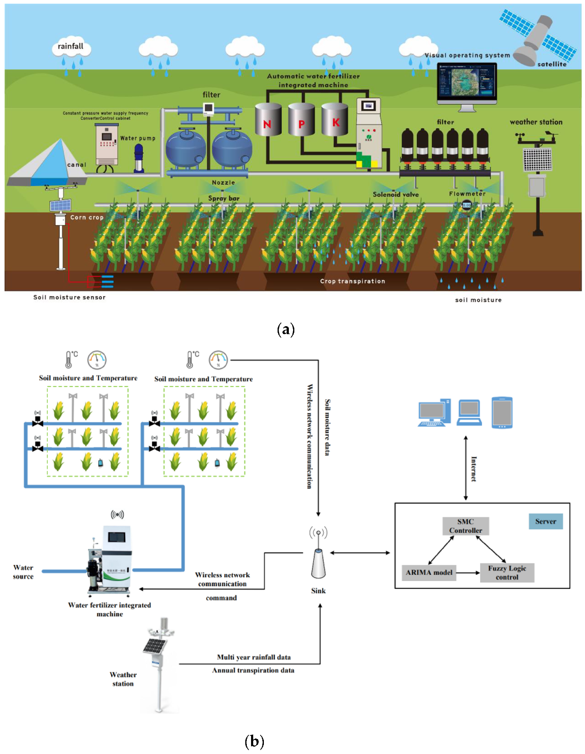
Fertigation system working principles are easiest to understand by following one irrigation cycle. Water flow is established, a prepared fertilizer solution is injected at a controlled rate, the mixed solution reaches the selected zone, and irrigation continues long enough to clear the intended delivery path after injection stops. Sensors observe parts of this process; a controller uses defined rules to operate pumps and valves. Neither a soil probe nor a cloud display performs those hydraulic functions by itself.
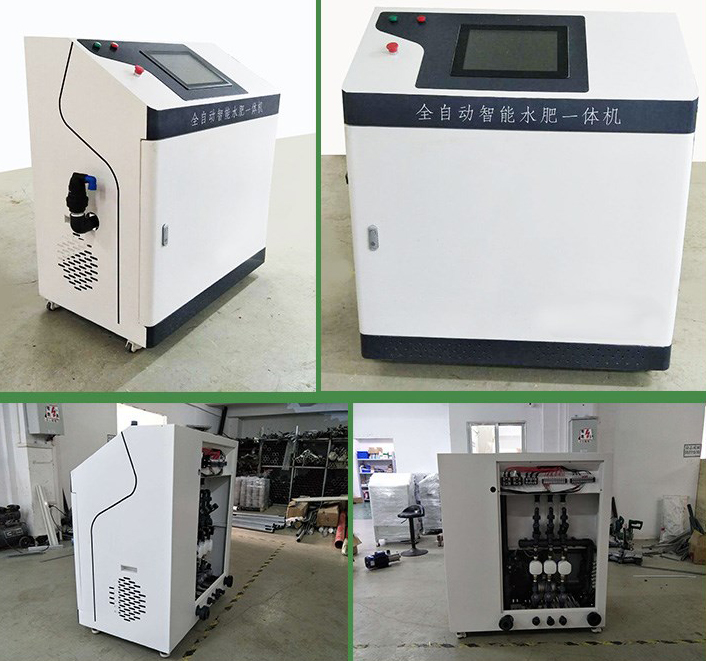
The water-delivery loop maintains the intended zone flow and pressure. The injection loop controls how much stock solution enters that water. The agronomic review uses soil, substrate, drainage and crop observations to adjust later irrigation and nutrient programs. Combining all three into a single rule such as "low soil reading means add fertilizer" overlooks important delays and measurement limits.
| Part of the process | Typical feedback | Decision it can support |
|---|---|---|
| Water delivery | Flow, pressure and relevant valve or pump status | Whether the selected zone has a usable irrigation supply |
| Injection and mixing | Stock-solution use, injection flow and mixed-solution EC/pH where configured | Whether dosing follows the approved recipe and control limits |
| Root-zone response | Moisture, temperature, conductivity and suitable crop or laboratory observations | Whether later events or the agronomic program need adjustment |
A system can operate with scheduled dosing and monitored feedback without automatically changing every setpoint. State which values are displayed, which generate alarms and which are allowed to influence an actuator. This distinction is important when connecting an existing irrigation installation to new sensors.
At the start of an event, the controller selects the intended irrigation zone and establishes water delivery according to the installed hydraulic sequence. Check that flow and pressure are suitable before allowing stock solution into the line. A pump command or an illuminated valve indicator is not proof that water is reaching the emitters.
Injection should stop when the required irrigation flow is lost. Protection against backflow must also be part of the installation, rather than relying on the operator to notice a stopped pump. University of Minnesota Extension's publication "Chemigation safety measures" identifies risks including return flow toward the water source and continued injection after irrigation stops. The appropriate devices depend on the water source, system arrangement and applicable local requirements.
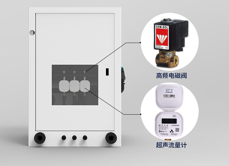
The control enclosure below illustrates electrical equipment associated with an installation. Its appearance does not define the operating sequence or establish a protection rating for the entire system. Specify the controller, output circuits and installed protective functions separately from the sensing instruments.
A Venturi injector creates suction through a pressure difference. Its injection rate can change when the hydraulic conditions change. A dosing pump provides another method, but its achievable flow, control range and pressure capability still need to match the application. FAO's chapter on fertigation describes injector arrangements and the sensitivity of Venturi operation to pressure variation.
Keep the stock-solution concentration and the injection ratio distinct. One describes how much fertilizer is dissolved in the tank; the other describes how much of that solution enters the water. Changing either changes the delivered concentration. Label the ratio convention, because stock volume per water volume and stock volume per final mixture volume are not identical definitions.
For a hypothetical mass-balance example, a stock solution containing 100 g/L of a named fertilizer product is injected at 20 L/h into 2,000 L/h of water. It supplies 2,000 g/h of that product. Assuming additive volumes, the final concentration is approximately 0.990 g/L in 2,020 L/h of mixed solution. This is a product concentration, not an elemental nitrogen concentration or a crop recommendation.
Check injection under the actual zone conditions. Measure the stock volume used and the water volume delivered over the same interval, then compare their ratio with the intended setting. The University of Maryland Extension irrigation check-up guidance describes this volumetric verification. A setting on a dial is not a substitute for checking what was delivered.
Fertilizer suitability depends on solubility, formulation and compatibility with the source water and equipment. Materials that are individually soluble can still form deposits when concentrated together. Prepare and combine solutions according to their documented compatibility and the agronomic program. Do not assume that adding a finer filter makes every fertilizer mixture suitable for injection.
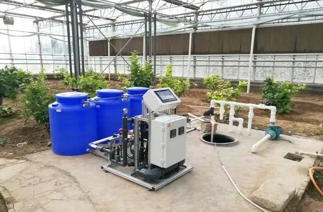
The layout below separates water supply, preparation and delivery functions. The number of stock tanks or dosing channels should follow the required compatible solutions, not an assumed standard of three or five channels for every crop. Provide access for tank inspection, cleaning and identification of each connected line.

A mixed-solution EC sensor should see a representative mixture, not an unmixed plume immediately beside an injection point. Its reading includes the conductivity of the source water and all contributing dissolved ions. EC can help track concentration consistency for a known formulation, but it cannot independently identify nitrogen, phosphorus and potassium or verify their ratio.
pH is another measurement, not a replacement for EC. It describes acidity or alkalinity on the pH scale, while the amount of chemical needed to change it also depends on buffering. A controller should not derive a universal dosing quantity from a pH value alone. Any chemical-adjustment function needs a defined recipe, compatible equipment and appropriate operating safeguards.
Mixing and transport create delay. If the controller makes repeated large corrections before the previous dose reaches the sensor, the result can overshoot. Establish the response of the actual tank, pipe and sample arrangement before tuning automatic control. A sensor's response-time specification excludes much of this hydraulic delay.
For example, a 30 L effective mixed volume supplied at 10 L/min has a nominal volume-to-flow time of three minutes. This simple calculation is not a validated settling time: real mixing, bypass flow, sampling and the sensor's response can change the observed behavior. It is a reason to test the sequence rather than setting the control interval from a communications speed.
Water takes time to reach a buried probe, and the response depends on its depth and position relative to the emitters. A moisture threshold can inform an irrigation request, but immediately starting and stopping a pump around one fluctuating value can cause short cycling. Use a defined operating sequence with an appropriate separation between start and stop conditions and limits on an event's duration or volume.
The NiuBoL NBL-S-TMCS provides soil temperature, volumetric moisture, conductivity and a salinity output through RS485 Modbus RTU. It can support review of water and salt trends at the monitored location. It does not calculate a fertilizer recipe or identify individual nutrients from conductivity.
| NBL-S-TMCS item | Specified value | How to use it in this process |
|---|---|---|
| Soil temperature | -40 to 80 degrees C; 0.1 degree C resolution; +/-0.5 degrees C accuracy | Record the thermal context of root-zone measurements. |
| Soil moisture | 0-100% volumetric moisture; 0.1% resolution | Compare wetting and drying at a defined depth and position. |
| Conductivity | 0-10000 uS/cm; 1 uS/cm resolution; compensation range 0-50 degrees C | Follow conductivity trends under comparable moisture conditions. |
| Salinity output | 0-8000 mg/L; 1 mg/L resolution | Retain the sensor's output definition; do not identify individual salts from it. |
| Supply and interface | 5-24 V DC or 12-24 V DC configuration; RS485 Modbus RTU | Match the ordered supply version and controller input configuration. |
| Installation | IP68 sensor; standard 5 m cable; all electrodes in contact with the medium | Protect the cable and maintain consistent probe contact. |
Drying soil changes the conductive path as well as the water content. An EC difference before and after irrigation cannot automatically be assigned to a change in nutrient quantity. Compare observations with their moisture and temperature context, and use suitable laboratory or crop assessments when the decision concerns nutrient availability. A direct-reading NPK output also needs its method and interpretation established before it is used in fertilizer decisions.
Stop stock-solution injection before completing the planned water-delivery sequence. The required clearing period depends on the path volume, flow and distribution arrangement; a fixed number of minutes is not appropriate for every system. Verify that the intended solution reaches the distant outlets and that the final water phase clears the relevant lines without applying an excessive additional irrigation volume.
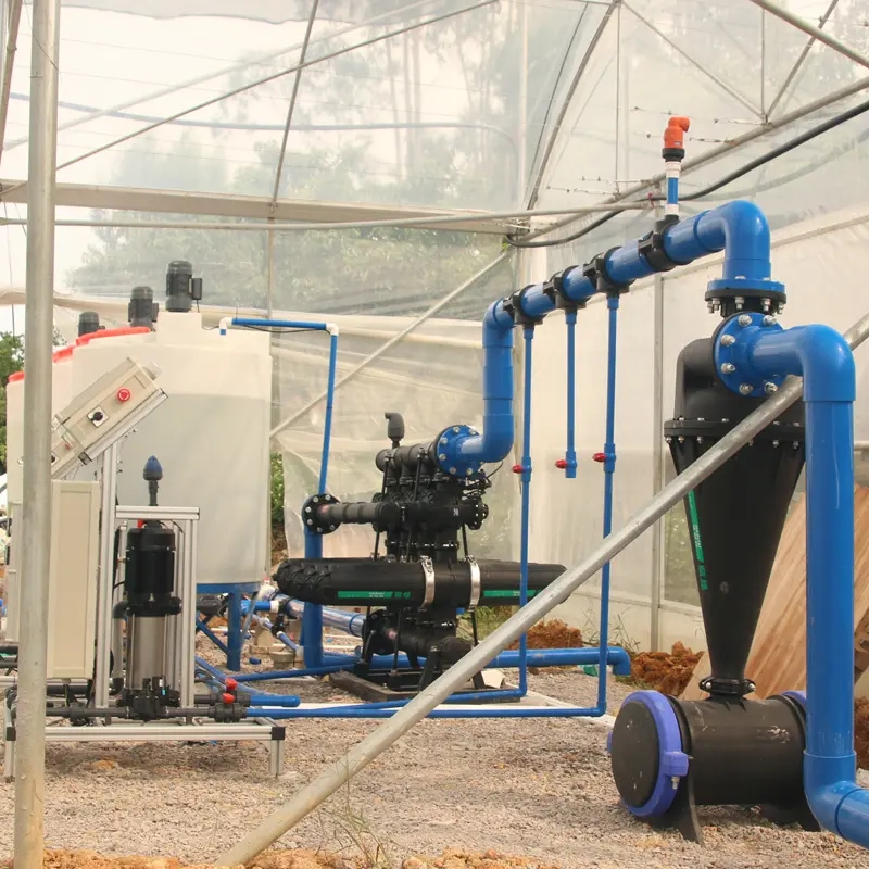
The photographed filtration and supply equipment illustrates another limit of feedback control: a correct mixture at the headworks cannot correct clogged or unevenly supplied emitters. Inspect pressure and delivered flow at representative locations in the zone. Separate a mixing problem from a distribution problem before changing the fertilizer setting.
A practical arrangement is soil and water sensors connected to a PLC, RTU or irrigation controller, with compatible gateway equipment providing remote records where needed. RS485 Modbus RTU carries measurements and supported commands; it does not directly energize a pump or guarantee that a valve changed position. Electrical outputs and actual process feedback are separate parts of the design.
Define the response to unavailable or stale measurements locally. Depending on the operating mode, the system may suspend automatic dosing, follow an authorized limited schedule or require operator intervention. It must not silently treat a disconnected sensor as zero moisture or zero nutrient concentration. Remote access should not be the only path for stopping injection.
For a strawberry or other high-value crop installation, keep crop-specific recipes under agronomic control. Root-zone observations can reveal slow drainage, uneven wetting or salt accumulation, but they do not justify a universal daily frequency or a fertilizer ratio for every growth stage. Test the water-delivery and dosing sequence before allowing sensor-based adjustments to the program.
It can be an input to an appropriate control sequence, but soil response is delayed and spatially variable. Use validated thresholds, event limits and suitable start/stop separation. A single probe crossing a value does not establish that the entire zone has received the intended water depth.
Not without establishing the measurement method and a validated agronomic model. Nutrient availability, crop demand and dosing are different quantities. Do not substitute an unexplained sensor number for soil or solution analysis and a crop nutrient program.
The zones can impose different flow and pressure conditions, particularly important for a Venturi injector. Check stock uptake under each intended operating condition. A calibration performed on one zone may not describe another.
No. Different ions and source-water compositions can produce similar conductivity. Use EC to assess the defined mixture with a known recipe and suitable reference checks, not as a chemical identification method.
Observe an actual zone cycle, including established water flow, stock uptake, mixed-solution response, injection stop and the final water phase. Verify the response to lost flow and unavailable measurements using an approved test procedure. Record delivered quantities rather than accepting only a screen demonstration.
Fertigation system working principles combine controlled water delivery, measured injection and delayed feedback from the solution and root zone. Each part needs a defined role. NiuBoL sensors can supply compatible observations for that process; send the measured medium, required range, controller interface and installation arrangement when selecting sensing equipment for a new or existing system.
Related recommendations
Sensors & Weather Stations Catalog
 Agriculture Sensors and Weather Stations Catalog-NiuBoL.pdf
Weather Stations Catalog-NiuBoL.pdf
Agriculture Sensors Catalog-NiuBoL.pdf
Water Quality Sensor Catalog-NiuBoL.pdf
Related products
 Combined air temperature and relative humidity sensor
 TDR Soil Moisture & Temperature Sensor for irrigation| RS485 |4-20mA| NBL-S-THR
 Soil pH sensor RS485 soil Testing instrument soil ph meter for agriculture |NBL-S-PH
 Wind Speed sensor Output Modbus/RS485/Analog/0-5V/4-20mA
 Tipping bucket rain gauge for weather monitoring auto rainfall sensor RS485/Outdoor/stainless steel
 Pyranometer Solar Radiation Sensor 4-20mA/RS485


Screenshot, WhatsApp to identify the QR code
WhatsApp number:+8615367865107
(Click on WhatsApp to copy and add friends)

