





— Blogs —
—Products—
 Consumer hotline +8618073152920
WhatsApp:+8615367865107
Address:Room 102, District D, Houhu Industrial Park, Yuelu District, Changsha City, Hunan Province, China
Product knowledge
Time:2025-09-09 16:55:15 Popularity:1114
Quick Answer: Duct sensors measure conditions in the air stream passing a ventilation point, not automatically throughout the occupied room, crop canopy or stored product. For HVAC and agricultural applications, choose the sensing location and controller input around the intended decision. A temperature/RH probe does not also measure air velocity, airflow volume, CO2 or hazardous gases unless those sensing functions are separately included.

Supply air shows what the ventilation equipment delivers. Return air shows a mixture returning from the served space. Neither necessarily captures a warm corner of a greenhouse, conditions beside livestock or moisture within stored grain. Start by deciding whether the controller needs an equipment operating value, a representative space value or both.
Consider a greenhouse air handler. A duct temperature and humidity sensor downstream of its mixing section can check delivered air, while a shaded sensor near the crop provides the growing-zone measurement. If only the duct point is installed, a controller may report satisfactory supply conditions while the canopy remains too humid because air distribution is poor.
That distinction also prevents procurement mistakes. A longer probe may reach a more representative part of a duct, but it does not expand the measurement into an entire building. Multiple zones need a layout review, not simply a higher accuracy figure on one transmitter.
Temperature is used for heating, cooling and air-mixing decisions. Relative humidity describes water vapour relative to saturation at the measured air temperature. Air velocity requires its own sensing element, and volume flow additionally needs duct area and a representative velocity estimate. Indoor air quality and gas safety require sensors matched to the particular substance and application.
Do not use an outdoor cup anemometer as an unqualified substitute for an HVAC duct velocity probe. Similarly, an ambient particle monitor is not automatically suitable for dusty extraction ductwork. Duct velocity, dust loading, pressure, condensation and access for cleaning can change the appropriate instrument design.
A combined temperature/RH transmitter is useful when both measurements describe the same air parcel. The controller can derive a dew-point estimate from them, but the transmitter is not thereby a surface-condensation detector. To evaluate a cold duct wall or product surface, compare that surface temperature with the relevant air dew point.

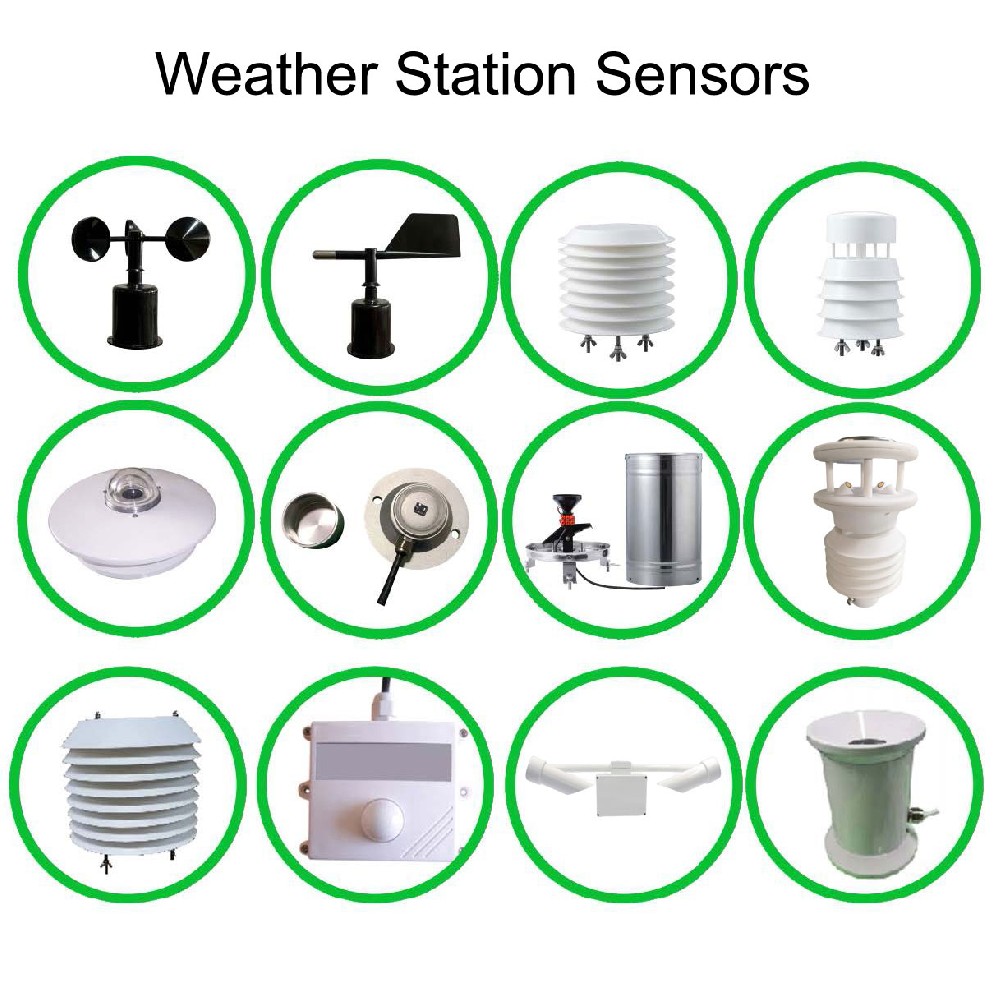
For an RS485 duct transmitter configuration with a stainless-steel probe filter, the following values provide a concrete comparison. They apply to that configuration, not to every NiuBoL ambient sensor or every housing pictured on this page. Match probe length, electronics limits and output before selecting a replacement.
| Parameter | RS485 duct temperature/RH configuration |
|---|---|
| Probe temperature range | -40 to 80 degrees C |
| Temperature accuracy | +/-0.5 degrees C at 25 degrees C |
| RH range | 0-100% RH; range coverage does not establish tolerance of persistent liquid condensation |
| RH accuracy | +/-3% RH at 60% RH and 25 degrees C |
| Electronics environment | -40 to 60 degrees C; 0-80% RH |
| Supply and consumption | 10-30 VDC; maximum 0.1 W for this configuration |
| Output | RS485 / Modbus RTU |
| Display resolution | 0.1 degree C and 0.1% RH; resolution is not measurement accuracy |
| Response at 1 m/s air velocity | Temperature up to 25 seconds; RH up to 8 seconds |
| Probe filter | 25 micrometre stainless-steel filter; not a guarantee against all contamination |
| Protection and cable | Specify enclosure IP rating, gland, cable jacket and length for the actual installation; do not infer them from the sensing range |
The distinction between probe and electronics limits is important in hot supply ducts. A probe rated to 80 degrees C does not authorize putting a 60-degree-C electronics housing inside the same hot air stream. Keep the housing in a suitable environment and evaluate heat conducted through the insertion assembly.
Response figures also depend on exposure. A one-second data refresh is not a one-second physical response. Low air movement, a fouled filter or protective additions can slow the observed change. Select controller filtering and alarm delays with that physical behavior in mind.
Air immediately after a mixing junction can remain stratified. A probe on the warm side and another on the cool side may disagree without either being faulty. Choose a location with adequate mixing or use a measurement arrangement designed to represent the section. Do not apply a calibration offset to conceal a persistent placement error.
Avoid direct spray from humidifiers, drain carryover and contact between the sensing tip and the duct wall. For a humidity-controlled process, decide whether the point is intended to measure air before or after conditioning. Put that identity in the controller tag so later maintenance does not reverse the interpretation.
Use the mounting flange and insertion depth appropriate to the ordered probe. Seal the penetration against leakage without blocking the filter or loading the sensing stem. Leave clearance to remove the probe and open the terminals; placing the transmitter behind inaccessible insulation makes routine checks unnecessarily disruptive.
Support the cable outside the duct, use a suitable gland and protect the housing from washdown or condensate run-off. An ingress-protection rating on a closed enclosure does not make an open humidity sensing surface waterproof. Do not coat the filter with sealant or wrap it in a material that prevents air exchange.

Dust, moisture and cleaning chemicals challenge the probe and filter. Duct sensors can check incoming or extracted air, while measurements in the occupied zone reveal what the animals experience. Select gas detection separately where needed; a temperature/RH value cannot establish ammonia concentration or replace a dedicated safety system.
Use inlet-air temperature and RH to assess the air available for aeration, with grain temperature and suitable product-moisture information where the storage strategy requires them. Duct RH is not grain moisture content. A moisture percentage assigned directly from duct humidity would misrepresent the stored product.
Supply-air measurements help identify a heater, cooler or humidifier that is not producing the expected condition. Canopy measurements remain necessary for evaluating the growing environment. When both disagree, inspect airflow distribution and sensor exposure before simply increasing heating, fogging or ventilation.
A return duct provides an aggregate value that can mask zones outside specification. Pair it with room measurements where product quality or zone control depends on local conditions. A duct sensor does not by itself establish cleanroom qualification, storage compliance or a validated process.
Air warming without added moisture can show lower relative humidity because its saturation pressure increases. For an illustrative near-atmospheric case, air at 20 degrees C and 60% RH has a dew point of about 12 degrees C. Heating that air to 25 degrees C without adding water reduces RH to approximately 44%, while the dew point remains close to 12 degrees C.
If a surface in contact with the original air is below that dew point, condensation is possible. The same 60% RH reading does not imply condensation on every surface. Examine air temperature, surface temperature, local airflow and uncertainty together before defining an alarm.
When comparing two probes, allow them to experience the same well-mixed air and stabilize. A recently handled portable reference, a probe near a cold wall and a sensor exposed to a warm electronics housing can disagree for physical reasons. Capture those conditions before deciding that either instrument needs recalibration.
For an RS485 / Modbus RTU unit, verify supply polarity, A/B terminal designation, serial format, unique address and register scaling. Use a suitable bus layout, cable routing and termination for the installation. An unchanged address shared by two transmitters can look like intermittent sensor failure.
A PLC or building controller must support the selected protocol. RS485 is an electrical interface, not proof of native BACnet or Modbus TCP support. Where the existing system requires a different interface, specify the gateway and its point mapping rather than assuming that changing two wires converts the protocol.
For analog replacements, check whether the controller expects 4-20 mA, 0-10 V or another signal, and whether the temperature span matches. Two transmitters with the same current output but different temperature spans are not drop-in equivalents. Test the controller conversion independently before adjusting a sensor to match a displayed number.
Compare the local value, PLC value and trend record after stabilization. Apply a controlled change appropriate to the installation and observe the direction, response and recovery. Test a disconnected sensor through an approved commissioning procedure to confirm that the controller identifies loss of data instead of retaining a normal-looking value indefinitely.
Inspect the filter for obstruction and compare as-found readings before cleaning or adjustment. Use cleaning methods compatible with the sensing element; solvents, pressure washing and abrasive cleaning can cause damage. Base service intervals on actual dust and moisture exposure, with additional checks after washdown, chemical treatment or condensation events.
For a replacement or new installation, send NiuBoL a duct sketch, insertion length, expected air conditions, contamination risks and controller input details. A temperature and humidity sensor inquiry becomes more useful when it identifies whether the reading controls supply air, a return stream or the served space.
Only if the control design has established that its location represents the condition of interest. Supply air and canopy air commonly answer different questions. Use a growing-zone point where crop conditions determine the control target.
No. Temperature and RH measurement do not establish velocity or volume flow. Airflow verification requires the appropriate velocity or differential-pressure arrangement, duct geometry and a method that represents the section.
Not automatically. Liquid water can alter the response and recovery of a humidity element. Define condensation, spray and cleaning exposure separately and select a suitable installation or instrument design rather than relying on the numerical range alone.
They may be sampling different air. Investigate supply/return position, mixing, wall temperature, airflow and stabilization before applying an offset. Compare both instruments in the same stable environment if calibration is in doubt.
Probe length, required accuracy conditions, output version, display, housing exposure and connector or cable requirements affect the supplied configuration. Provide the old signal span and controller details so the quote includes compatibility, not just a similar-looking enclosure.
A temperature/RH transmitter cannot detect a hazardous gas. Select gas-specific equipment with the required application suitability and safety approvals. Its alarm and ventilation response must be engineered separately.
Duct sensors add value when their location corresponds to the control decision. Distinguish air-stream conditions from room or crop conditions, separate temperature/RH from airflow and gas measurement, and test the complete controller conversion. NiuBoL can review the duct conditions and existing interface to identify a suitable sensing arrangement.
Related recommendations
Sensors & Weather Stations Catalog
 Agriculture Sensors and Weather Stations Catalog-NiuBoL.pdf
Weather Stations Catalog-NiuBoL.pdf
Agriculture Sensors Catalog-NiuBoL.pdf
Water Quality Sensor Catalog-NiuBoL.pdf
Related products
 Combined air temperature and relative humidity sensor
 TDR Soil Moisture & Temperature Sensor for irrigation| RS485 |4-20mA| NBL-S-THR
 Soil pH sensor RS485 soil Testing instrument soil ph meter for agriculture |NBL-S-PH
 Wind Speed sensor Output Modbus/RS485/Analog/0-5V/4-20mA
 Tipping bucket rain gauge for weather monitoring auto rainfall sensor RS485/Outdoor/stainless steel
 Pyranometer Solar Radiation Sensor 4-20mA/RS485


Screenshot, WhatsApp to identify the QR code
WhatsApp number:+8615367865107
(Click on WhatsApp to copy and add friends)

