

— Blogs —
—Products—
 Consumer hotline +8618073152920
WhatsApp:+8615367865107
Address:Room 102, District D, Houhu Industrial Park, Yuelu District, Changsha City, Hunan Province, China
Product knowledge
Time:2026-03-08 15:46:26 Popularity:549
Soil moisture monitoring system selection starts with the observation method: a portable instrument used during field visits, a permanently installed soil profile, or a network of stations reporting to a management platform. These options answer different questions. Choose the observation method first, then compare sensors, recorders and communications; otherwise a convenient handheld reading may be mistaken for a continuous root-zone record.
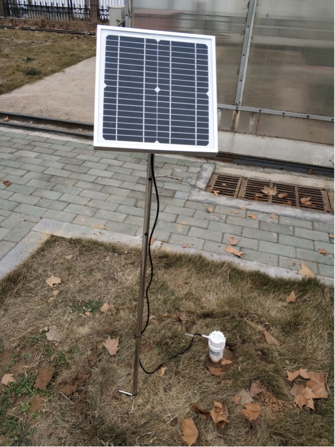
A portable survey is useful for checking spatial variation, investigating a suspected dry area and choosing permanent monitoring positions. It does not capture what happens between visits. A fixed probe records changes at one installed location, including wetting and drying events that staff may miss. It does not eliminate the need to check whether that location represents the area being managed.
| Approach | Suited to | Limit that affects the purchase |
|---|---|---|
| Portable measurements | Comparing locations during a field survey | Visit timing and insertion consistency affect comparisons |
| Fixed single-depth probes | Observing a defined layer at several positions | More cables and installation points may be required |
| Fixed multi-depth tube | Following a vertical moisture and temperature profile | Depth positions are physical sensing locations, not software-created channels |
| Networked observation stations | Comparing management zones over time | Each station still needs a representative location and maintained data route |
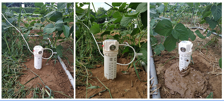
Divide the field by soil, terrain and irrigation management before deciding the station count. Two areas supplied by the same pump may still have different soil texture or drainage. Conversely, installing several tubes close together beside a convenient power source can provide little information about a distant block that dries differently.
For drip irrigation, record the probe's position relative to the emitter and plant. A tube inside the wetted bulb and one between rows may both work correctly while showing different curves. For a trial, keep that position consistent between treatments. For an operational field, choose a position that answers the intended management question rather than seeking a visually tidy installation.
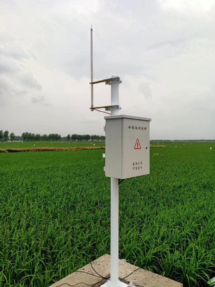
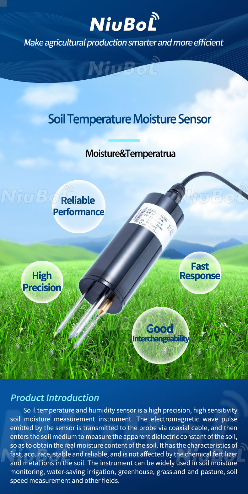
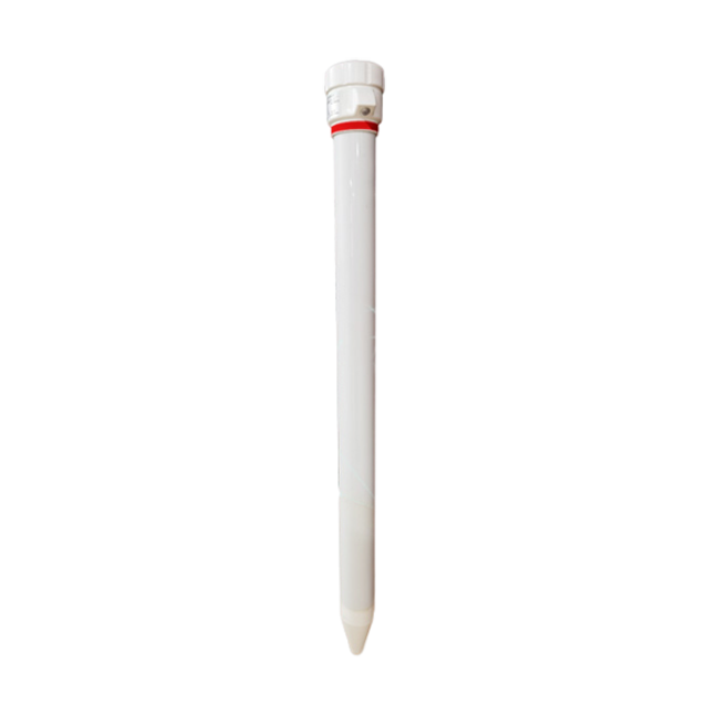
The NBL-S-TMSMS tubular multi-depth sensor uses FDR to estimate volumetric water content and measures temperature at selected depths. It is a profile instrument, not a handheld console specification. Do not transfer a portable reader's display, USB connection or memory capacity to the tube unless that reader is part of the actual order.
| Parameter | NBL-S-TMSMS basis | Meaning for the project |
|---|---|---|
| Depth configuration | Standard 10, 20, 30 and 40 cm; other configurations by selection | Choose the required layers before purchasing |
| Moisture performance | 0.1% resolution; stated laboratory accuracy +/-3%, field accuracy +/-5% | A small displayed change is not automatically a significant field change |
| Temperature | -40 to 80 C; +/-0.5 C; 0.1 C resolution | Keep temperature and moisture as separate channels |
| Power and output | 12-24 VDC adapter option; RS485 Modbus; battery/wireless configurations available | Choose a complete compatible power and recorder arrangement |
| Housing | PVC tube with epoxy sealing; IP67 above-ground part, IP68 below-ground part | These ratings do not cover an unspecified cabinet or connector |
The moisture percentage represents volumetric water content, not automatically a percentage of field capacity or remaining plant-available water. Keep the output basis in the channel name and export. An irrigation application may calculate additional indices, but those require soil and root-zone information beyond the probe's raw output.
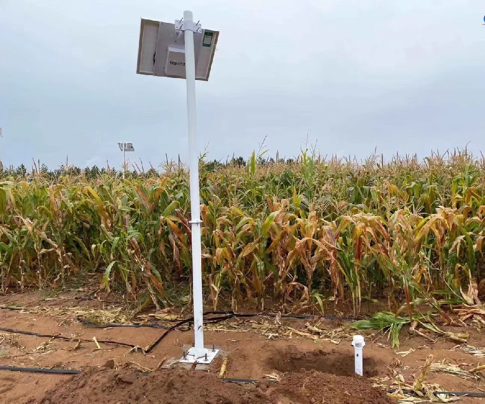
A dielectric instrument still depends on its relationship with the surrounding soil. An air gap, loose backfill or preferential flow down a disturbed hole can change the observed curve. Follow the selected probe's installation procedure, avoid forcing a tube into an unsuitable hole, and record any soil disturbance or backfilling method used.
After installation, examine a natural rain or a documented irrigation event. Ask whether near-surface and deeper channels respond plausibly for the soil and applied water. A rapid identical jump at every depth warrants investigation of water movement around the installation or channel mapping. It is not, by itself, proof of either good infiltration or a faulty sensor.
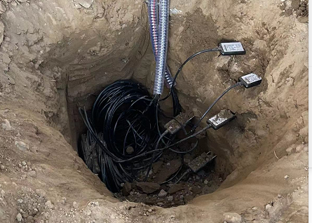
The individual probes shown in the installation photograph are a different arrangement from a tubular profile. They offer flexibility in placing separate sensing points, but their cables and soil contact need appropriate protection. Preserve the distinction in the equipment schedule so an installer does not apply a single-depth probe procedure indiscriminately to a multi-depth tube.
A handheld spot check near a fixed station should use a defined time, depth and position. Taking the portable reading beside a wet emitter while the tube stands farther away does not provide a valid instrument comparison. Allow for differences in sensing volume and avoid repeatedly disturbing soil immediately around the permanent installation.
If a project needs a reference water-content determination, agree the sampling procedure and laboratory method in advance. A gravimetric result is mass-based; converting it to volumetric content requires the relevant dry bulk density. Treating the two percentages as interchangeable can make a functioning sensor appear incorrectly calibrated.
For RS485 Modbus RTU integration, map every moisture and temperature register to its physical depth. Confirm scaling, signed temperature handling and missing-response behavior using the ordered protocol document. A successful serial exchange only shows that a device answered; it does not prove that the dashboard has assigned 10 cm and 40 cm correctly.
Keep raw measurements and installation history together. If a tube is moved, create a new installation reference rather than joining the new location silently to the old series. When a sensor is replaced, retain the replacement date and configuration. This is particularly important in trials where a shift in location can otherwise be mistaken for a treatment effect.
Inspect after cultivation, flooding, cable damage or a change in irrigation layout. A healthy supply voltage cannot establish that the probe still samples the same soil condition. Check for erosion around the tube, exposed cables and changes in emitter distance. Clean and inspect the solar supply according to its condition rather than assuming a fixed cleaning interval suits every site.
Review plots of each depth alongside rainfall or irrigation records. Long flat lines may reflect dry stable soil, a stuck value, a communication substitution or a disabled channel. Investigate those alternatives with timestamp and status information before replacing hardware. Scheduled calibration should follow the measurement requirement and observed behavior, not an unsupported rule that every installation needs quarterly adjustment.
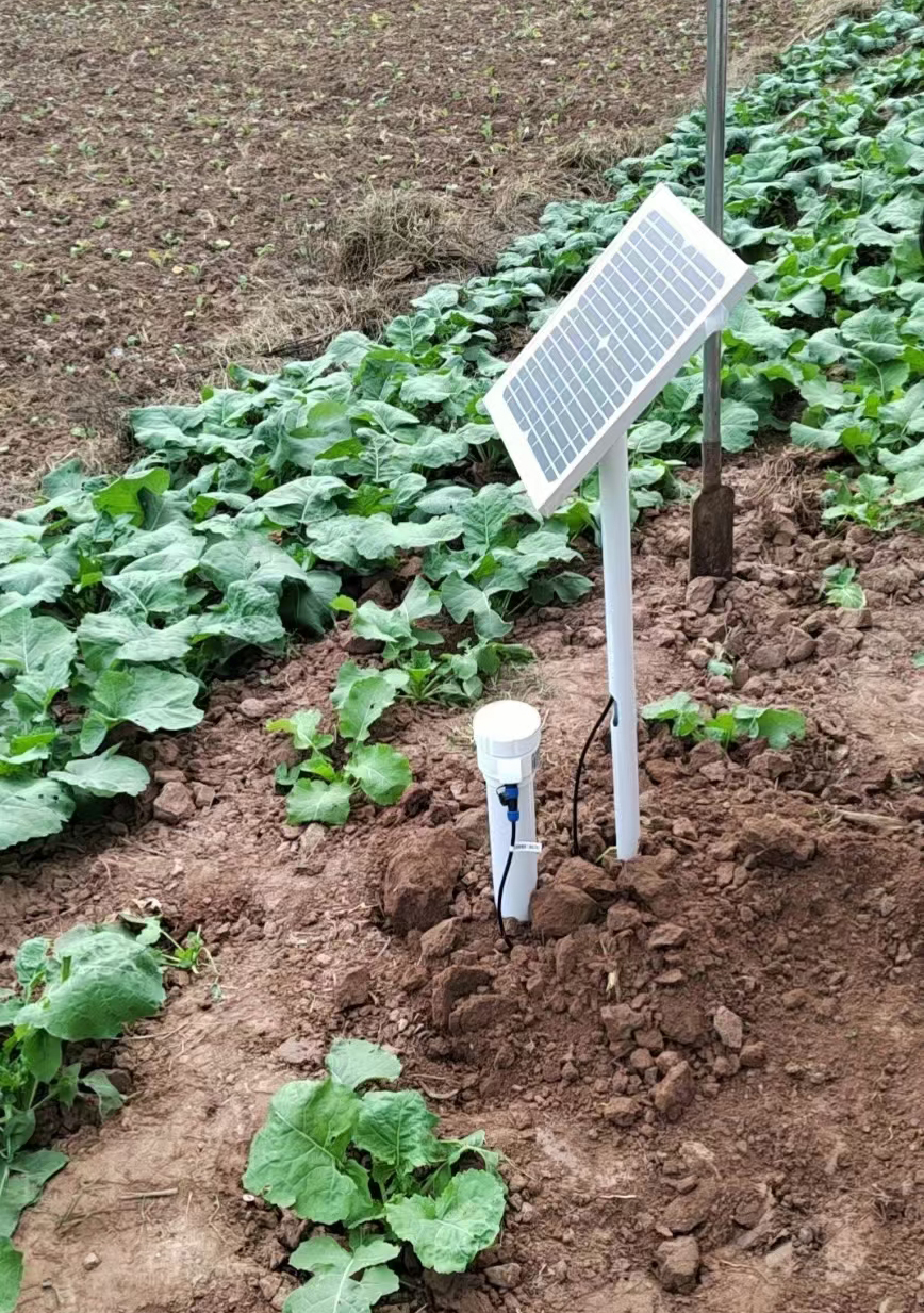
Ask NiuBoL to itemize the sensors, physical depth configuration, recorder, power supply, communications and installation accessories. If a portable reader is also required, list it separately with its compatible probes and export format. Do not compare a bare tube price with a solar-powered reporting station and conclude that the difference is only branding.
For a multi-site project, include the soil and irrigation zones, crop rooting requirements, expected cable routes and platform interface. Request a demonstration export with depth labels and timestamps. Define the commissioning comparison and access for seasonal inspection; these affect whether the purchased measurements remain useful after the first installation visit.
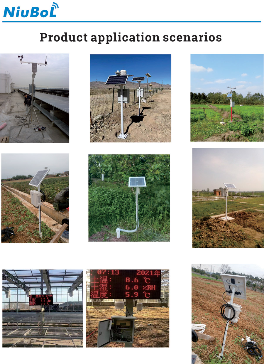
A handheld tester cannot provide continuous measurements between visits. Choose handheld measurements for field surveys and diagnostic visits. Use fixed observation when the project requires changes between visits, and combine the two when spatial checks are also important.
Software cannot create a sensing element that is not installed. Check the tube's physical depth configuration before ordering. Adding a new layer may require a different tube or an additional probe, with installation work and new channel mapping.
Different distances from the emitter, soil contact, sensing volumes and local soil variation can all contribute. Compare matching depths and times, inspect the wetting pattern and check register mapping before assuming that the difference is an accuracy failure.
No. The specified below-ground sensor section must be distinguished from the above-ground section, connections, logger and power cabinet. Apply each component's own rating and installation conditions; a sealed tube does not protect unrelated electrical equipment.
No. A wired sensor, a battery reporting version and a station with an external gateway are different arrangements. The quotation should identify where communication is implemented, which supply it uses and how the receiving platform obtains the data.
Verify depth identity, units, timestamps, physical installation and the response to a documented wetting event. Check any reference comparison against an agreed method. Communications success and a changing chart are useful checks, but do not establish representative soil measurement alone.
A soil moisture monitoring system should be selected by the spatial and time history the project needs. Portable surveys, separate probes and tubular profiles are complementary tools, not interchangeable specifications. Match NiuBoL sensors to the management zones, preserve physical depth identity and accept the installation through soil-response checks as well as data delivery.
 NBL-S-TMSMS-Tubular-Multi-depth-Soil-Moisture-Sensor-Instruction-Manual.pdf
NBL-S-TM-Soil-temperature-and-moisture-sensor-Instruction-Manual-4.0.pdf
NBL-S-THR-Soil-temperature-and-moisture-sensors-Instruction-Manual-V4.0.pdf
Prev:Agricultural Weather Station for Disaster Warning: Design the Alarm Response
Next:Soil Moisture Sensor Integration: Decode Readings and Protect Control Inputs
Related recommendations
Sensors & Weather Stations Catalog
Agriculture Sensors and Weather Stations Catalog-NiuBoL.pdf
Weather Stations Catalog-NiuBoL.pdf
Agriculture Sensors Catalog-NiuBoL.pdf
Water Quality Sensor Catalog-NiuBoL.pdf
Related products
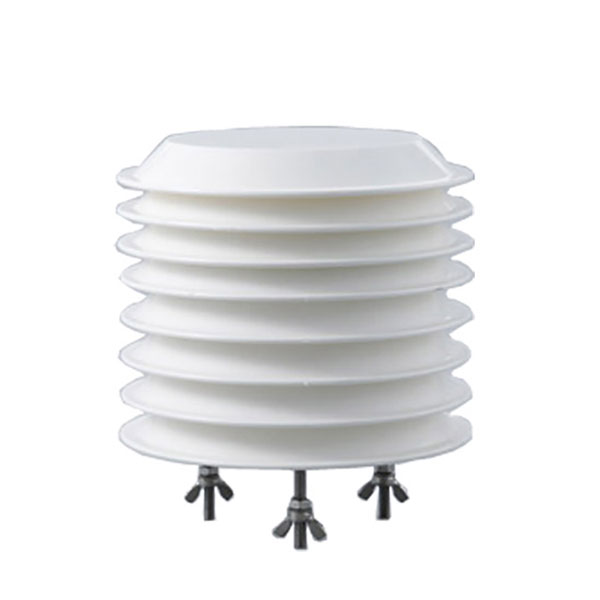 Combined air temperature and relative humidity sensor
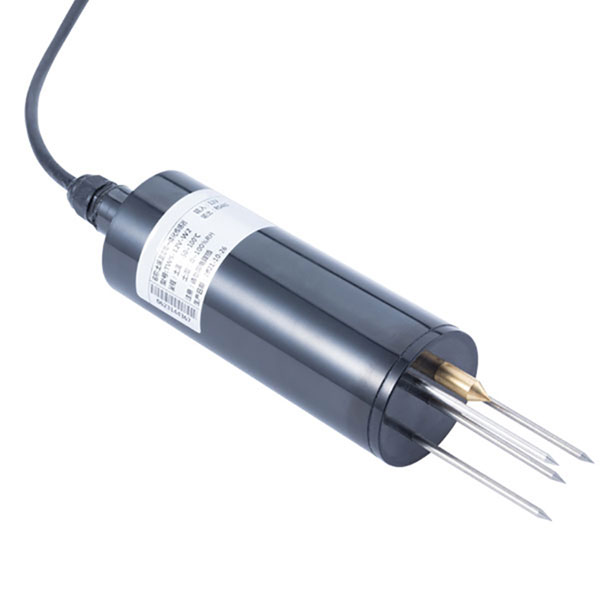 TDR Soil Moisture & Temperature Sensor for irrigation| RS485 |4-20mA| NBL-S-THR
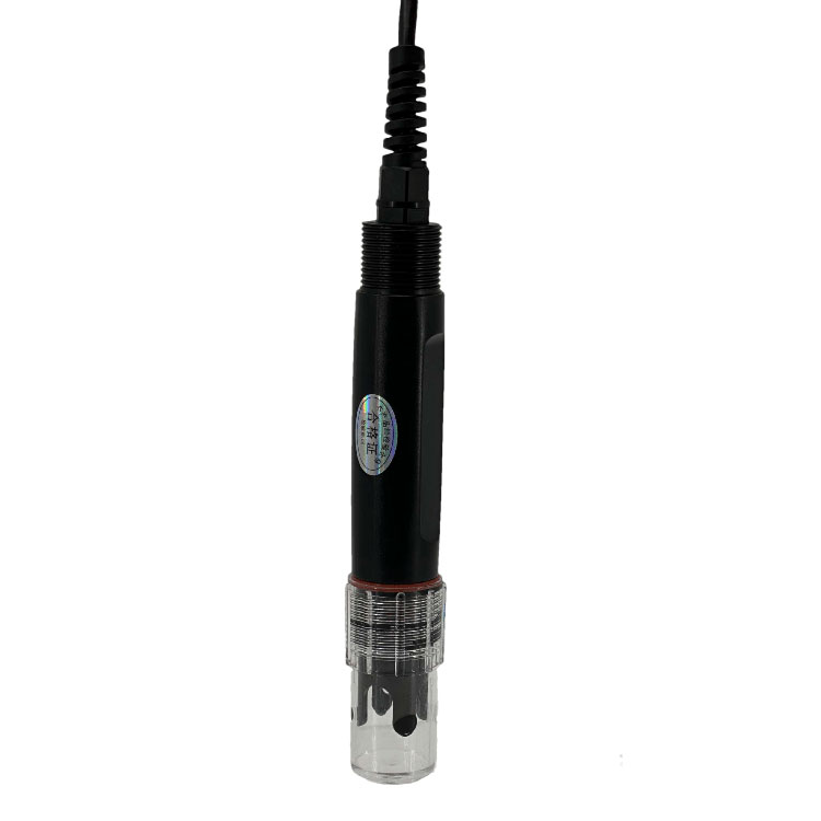 Soil pH sensor RS485 soil Testing instrument soil ph meter for agriculture |NBL-S-PH
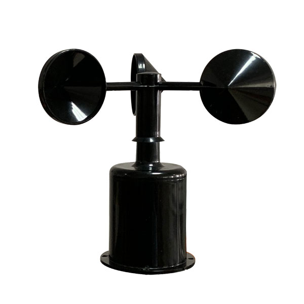 Wind Speed sensor Output Modbus/RS485/Analog/0-5V/4-20mA
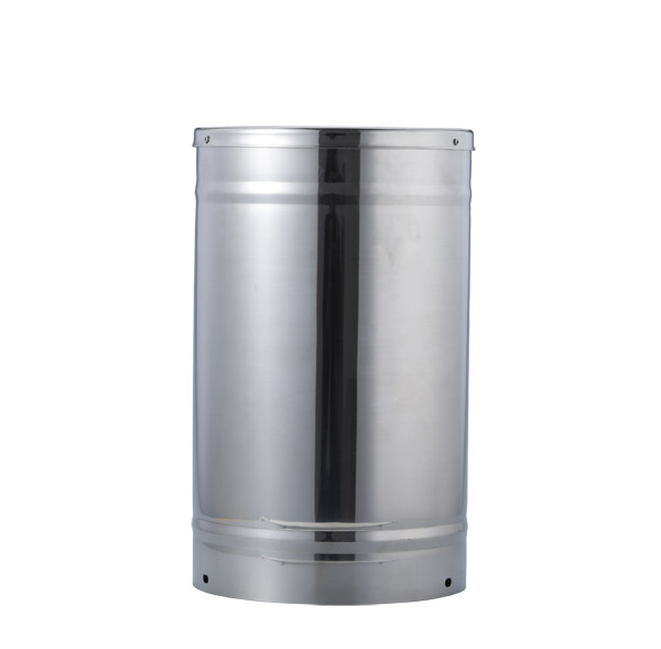 Tipping bucket rain gauge for weather monitoring auto rainfall sensor RS485/Outdoor/stainless steel
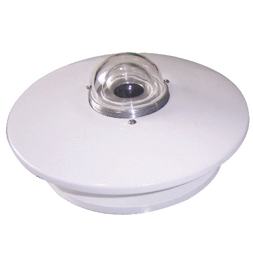 Pyranometer Solar Radiation Sensor 4-20mA/RS485


Screenshot, WhatsApp to identify the QR code
WhatsApp number:+8615367865107
(Click on WhatsApp to copy and add friends)