





— Blogs —
—Products—
 Consumer hotline +8618073152920
WhatsApp:+8615367865107
Address:Room 102, District D, Houhu Industrial Park, Yuelu District, Changsha City, Hunan Province, China
Product knowledge
Time:2026-02-03 14:44:48 Popularity:600
Quick Answer: A hydropower ecological discharge monitoring system must measure the intended release at a suitable section, including the lowest required operating flow. Water level, a camera view and successful transmission do not independently establish discharge. Select radar or submerged Doppler equipment from actual velocity, depth and site conditions, then verify the complete flow calculation against an appropriate reference. Reporting requirements and ecological release targets belong to the particular project, not to a sensor's communication protocol.
A hydropower site can have several water paths: an ecological release outlet, spill, turbine tailwater, leakage and tributary inflows. A downstream instrument may see more than one of them. Before choosing equipment, draw the water paths and identify which flows the monitoring point is intended to represent.
If an ecological release is monitored downstream of a confluence, extra water can conceal a reduced release at the outlet. Conversely, a section upstream of part of the release system can undercount it. Select a point where the relationship is clear, or measure the relevant paths separately and document the calculation.
Convenient access is necessary but not sufficient. A section beside a powerhouse may be easy to power and inspect yet have reversing or turbulent flow. A stable section farther away may be preferable if its contribution to the required measurement is understood. Resolve this hydraulic question before preparing the equipment list.
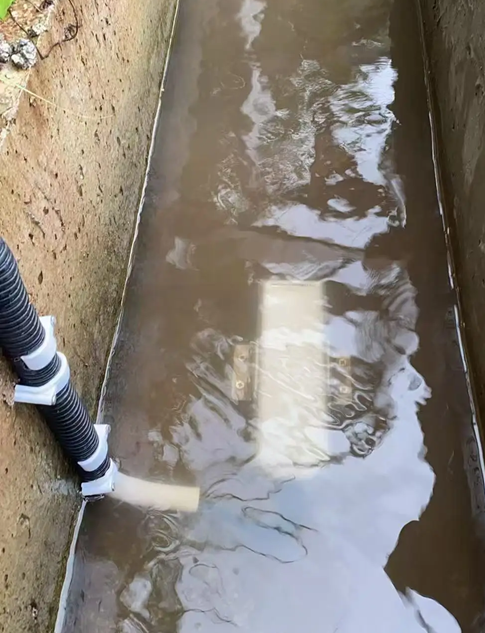
Low-flow verification deserves a separate test because the largest release is not always the difficult measurement. At low discharge, the water may spread into shallow threads, bypass part of the surveyed section, or move too slowly for the selected velocity instrument. A sensor that reads well during a larger test release may fail to represent the condition that matters most during normal ecological operation.
Separate a non-detection from a demonstrated zero. An exposed submerged probe, weak acoustic return, radar velocity below its range or a communication timeout should produce an identified invalid condition. Replacing those observations with zero can create a false low-flow alarm; holding the last acceptable value can conceal an actual interruption.
Assess uncertainty in flow units near the decision threshold. A sensor's velocity percentage is only one contribution; section area, depth reference and the conversion from sampled velocity to cross-sectional mean velocity also matter. There is no basis for claiming that a velocity accuracy specification alone guarantees the complete ecological discharge result.
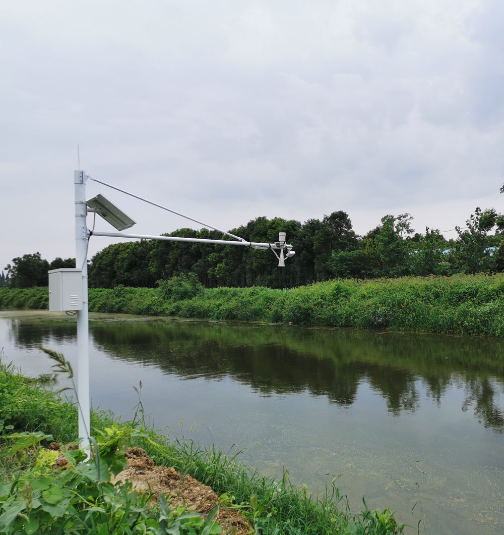
Non-contact radar flow measurement keeps the instrument above the water and reduces exposure to deposits on an immersed probe. It still needs an appropriate surface return, an unobstructed beam and a suitable relationship between surface velocity and the average velocity used in the calculation. Aerated jets, recirculation and very smooth slow water need particular attention.
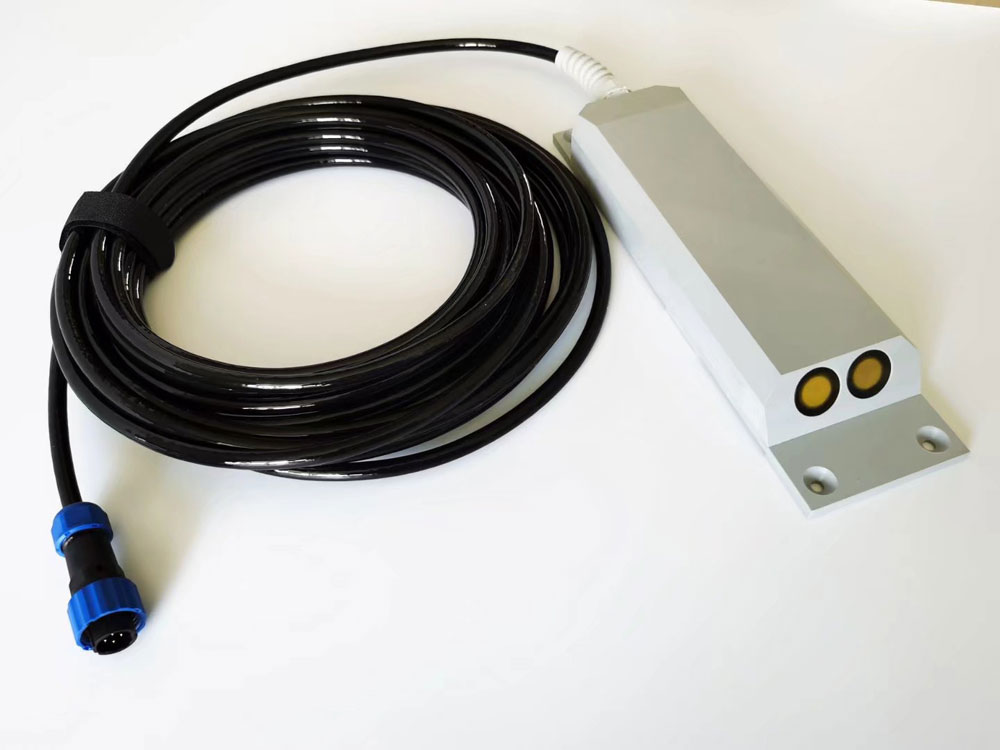
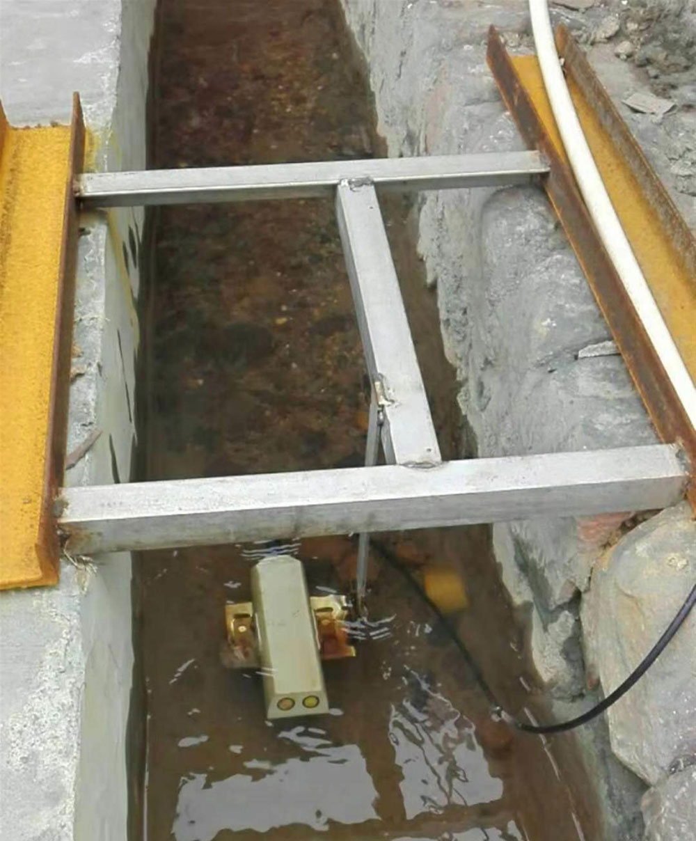
A submerged Doppler velocity meter samples moving acoustic reflectors within the water. It needs adequate submergence and a representative location. Installation in a sheltered pocket can produce a stable but unrepresentative reading. Sediment, vegetation, cable damage and blockage of the pressure reference are practical maintenance concerns.
| Low-flow consideration | NiuBoL radar configuration | Submerged Doppler option |
|---|---|---|
| Velocity range | 0.1-20 m/s. | 0.03-5 m/s for the unidirectional version. |
| Velocity accuracy expression | +/-2%; resolution 0.01 m/s. | +/-1.0% +/-1 cm/s. Confirm the percentage basis for acceptance. |
| Level measurement | Radar ranging 0.1-65 m; stated ranging accuracy +/-1 mm. | Pressure depth range 0.03-5 m; check offset and the required submerged position. |
| Output | RS485 Modbus RTU. | RS485 Modbus RTU; verify the purchased register map. |
| Power planning | 10-30 V DC; maximum 1.3 W for the radar instrument. | Match the supply and operating current to the selected revision; do not transfer the radar rating. |
| Environment and protection | Transmitter -40 to +80 degrees C, non-condensing; confirm enclosure and connector rating. | -10 to +60 degrees C and IP68 for this submerged configuration. |
| Cable requirements | Specify length, jacket, outdoor routing and sealed entries. | Preserve the pressure-reference vent path and protect the underwater cable route. |
The Doppler accuracy expression contains a 0.01 m/s additive term. At an illustrative velocity of 0.05 m/s, that term alone equals 20% of the velocity, before considering the percentage term or other uncertainties. This arithmetic is not a complete uncertainty assessment, but it explains why a lower range limit is not a promise of small relative error at that limit.
For a velocity-area arrangement, Q = A(h) x Vmean: discharge equals wetted area at depth h multiplied by cross-sectional mean velocity. A radar observation of surface velocity or a Doppler sample from part of the section needs an appropriate conversion to Vmean. Apply that conversion in the sensor or acquisition calculation as intended; do not apply the same correction twice.
As an illustrative example, a rectangular section 1.0 m wide with 0.15 m water depth has an area of 0.15 m2. If the independently established mean velocity is 0.20 m/s, discharge is 0.030 m3/s, or 30 L/s. The example assumes a rectangular wetted section and a representative mean velocity. It is not a release target or a reported project result.
At that shallow depth, a 0.01 m depth offset changes the calculated area by about 6.7%, even with velocity held constant. A small ranging specification does not remove errors in mounting elevation or the surveyed bed. Check the complete depth reference after installation, bracket movement or sediment deposition.
Compare calculated discharge with suitable field measurements across the operating conditions of interest. Include the ecological low-flow condition and relevant gate or tailwater states. If the same depth occurs with substantially different velocities, investigate whether a single level-discharge rating is appropriate. A one-time comparison at a high release cannot establish the low-flow relationship.

The measurement chain normally includes flow and level sensing, a PLC or RTU, local storage, a communication link and a receiving system. RS485 Modbus RTU connects the instrument to a compatible master. It does not automatically implement a regional reporting format, account credentials or the receiving server's acceptance rules.
For each channel, verify the unit, scale, direction convention and measurement time. Test the actual value at the instrument, controller and exported record. Avoid guessing a unit from a register label or assuming every model has the same counter representation. Establish how the cumulative volume behaves after a power interruption and how that behavior is represented in the report.
Store enough local information to investigate a low-flow event, including measured depth and velocity, calculated discharge and validity status. Mark restored observations with their original times. A delayed upload should not become a fresh measurement merely because it arrives after communications recover.
A camera can show an obstructed outlet, an unusual water path or a maintenance visit. It cannot independently quantify discharge from an ordinary image. Align image times with measurement times when images are included. Size video networking and storage separately from the low-bandwidth sensor records.
Commissioning should include a controlled comparison of the installed flow calculation, not only a successful network connection. Select safe test conditions with the operator and the responsible hydraulic specialist. Do not change an operational release simply to obtain a sensor demonstration without the required authorization.
Examine how the system responds when a velocity input becomes invalid while level remains available. Check a loss of communication separately from a power failure. Review whether local records are retained, whether the remote display shows their age and whether alarm handling recovers in a predictable way.
Reinspect the measuring section after a flood, bed movement, dredging or work on the outlet. A changed cross-section can invalidate a previously satisfactory calculation without changing the instrument's electronics. Keep the section survey and calculation settings associated with the period for which they were valid.
Solar sizing must include the real measurement schedule, RTU, communication equipment and any camera. A low-power sensor does not establish a low-power station. Assess available winter solar energy and required autonomy, then verify operation under the intended duty rather than assigning the same battery and panel to every site.
For a project inquiry, send NiuBoL the water-path sketch, intended measuring section, minimum discharge and depth, expected velocity, section dimensions, access conditions and required reporting interface. Include photographs of low-flow conditions, not only a full channel. This allows the proposed instrument and installation to be assessed against the difficult operating point before quotation.
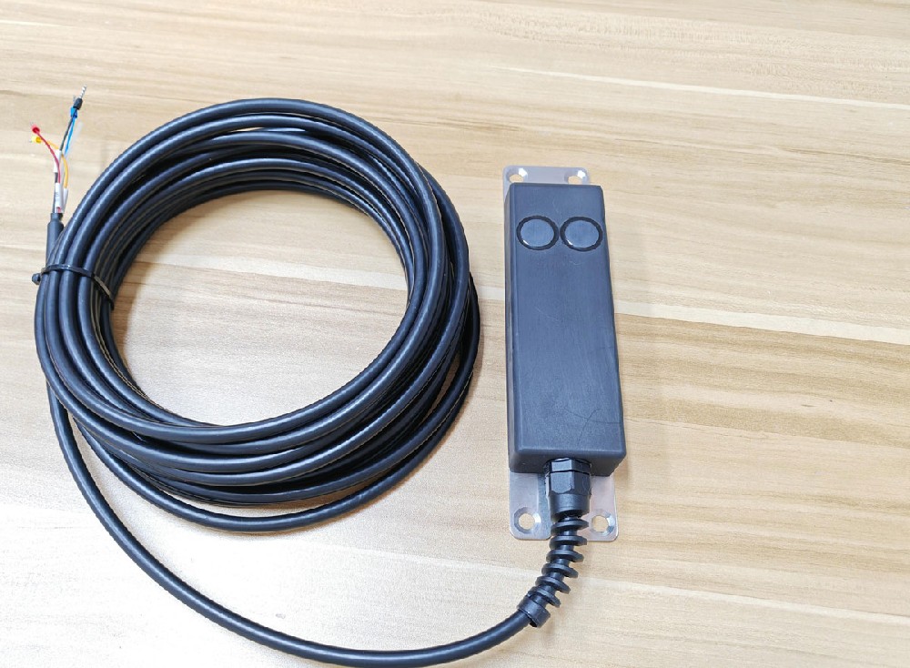
Only when the project definition and water paths make it representative. Turbine operation, spill, tributaries and other inflows can change what that point measures. Identify the required release and the contribution of each path before selecting the section.
No. Water may be moving below the instrument's velocity range or producing an inadequate return. Check validity, depth, operating conditions and an appropriate independent observation before classifying the event.
No. Its pressure range does not define the required cover above the acoustic elements. Check minimum submergence, sediment clearance and the sampled flow region for the selected configuration at the lowest expected depth.
No. Discharge also depends on the section survey, depth reference, velocity and conversion to cross-sectional mean velocity. Verify the installed calculation, especially where a small depth offset is a large fraction of the flowing depth.
Only if that platform accepts the implemented interface. Frequently an RTU or gateway must package records, authenticate and manage retries. Obtain the receiving specification and test the complete transfer rather than assuming sensor compatibility establishes reporting acceptance.
Not when the relationship changes across operating conditions. Agree on comparisons covering the required range and relevant hydraulic states, including low flow. Acceptance criteria should reflect the project's duty and reference method.
Section changes, probe deposits, movement of the mount, obstructed venting and radar beam interference can all alter the result. Inspect those causes alongside electrical checks, particularly after hydraulic events or construction work.
Hydropower ecological discharge monitoring depends on a representative water path and a verified low-flow measurement. Select the instrument from actual depth and velocity, maintain the section model, and make invalid or delayed records visible. NiuBoL flow instruments and acquisition equipment can form part of that arrangement; the complete hydraulic calculation and reporting chain still require project-specific acceptance.
Prev:Residual Chlorine Monitoring After a Water Supply Shutdown
Next:Hydropower Ecological Flow Monitoring: Radar or Doppler Site Choice
Related recommendations
Sensors & Weather Stations Catalog
 Agriculture Sensors and Weather Stations Catalog-NiuBoL.pdf
Weather Stations Catalog-NiuBoL.pdf
Agriculture Sensors Catalog-NiuBoL.pdf
Water Quality Sensor Catalog-NiuBoL.pdf
Related products
 Combined air temperature and relative humidity sensor
 TDR Soil Moisture & Temperature Sensor for irrigation| RS485 |4-20mA| NBL-S-THR
 Soil pH sensor RS485 soil Testing instrument soil ph meter for agriculture |NBL-S-PH
 Wind Speed sensor Output Modbus/RS485/Analog/0-5V/4-20mA
 Tipping bucket rain gauge for weather monitoring auto rainfall sensor RS485/Outdoor/stainless steel
 Pyranometer Solar Radiation Sensor 4-20mA/RS485


Screenshot, WhatsApp to identify the QR code
WhatsApp number:+8615367865107
(Click on WhatsApp to copy and add friends)

