





— Blogs —
—Products—
 Consumer hotline +8618073152920
WhatsApp:+8615367865107
Address:Room 102, District D, Houhu Industrial Park, Yuelu District, Changsha City, Hunan Province, China
Product knowledge
Time:2026-02-03 14:50:41 Popularity:603
Ecological flow monitoring at a hydropower station is an evidence problem as well as a measurement problem. The operator needs a defensible discharge value at the specified compliance cross-section, with enough raw level, velocity and station-health data to explain how the value was obtained. A non-contact radar flowmeter can be useful at an accessible open channel, but it is not a universal answer for tailraces, submerged conduits or highly disturbed water. NiuBoL supplies radar and Doppler measurement products; the project must choose a method against the actual section and the receiving authority's requirements.
Identify the physical point at which the discharge obligation is assessed. Water may leave through multiple channels, a bypass, turbine outlet or spillway; measuring one visible stream does not necessarily cover the total. Obtain the approved monitoring location, channel drawings, operating range and any required reporting interval from the project owner. If several paths contribute, state whether separate measurements or an agreed calculation will produce the reported total.
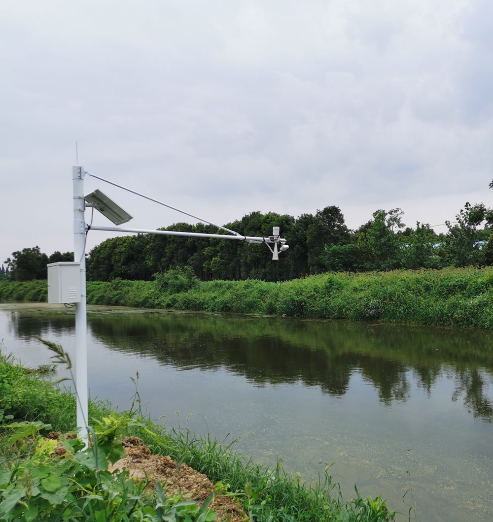
Survey the channel cross-section over the relevant stage range. Record bed shape, bank slope, controls, backwater, weed growth, sediment movement and the water levels at which a radar beam may encounter a wall or bracket. An open, stable section with a defined wetted area is easier to model than a turbulent tailwater immediately downstream of a turbine. The first photograph illustrates a river-side radar installation; it is not evidence that the shown section meets another plant's compliance specification.
Agree on the relationship between measured surface velocity and cross-sectional mean velocity. A radar instrument does not directly observe every point in the section. The conversion depends on geometry and flow distribution and should be checked with a suitable field reference over more than one operating condition. Do not replace this step with a universal coefficient copied from a sales sheet.
The section used for compliance may not be the most convenient place to mount a sensor. If the required reporting point is hydraulically disturbed, discuss with the owner whether an upstream or downstream measurement location can be accepted with a documented transfer relationship. That decision belongs in the approved monitoring plan, not in an installer note written after the equipment arrives. The quotation should identify the survey and any independent field measurement needed to establish that relationship.
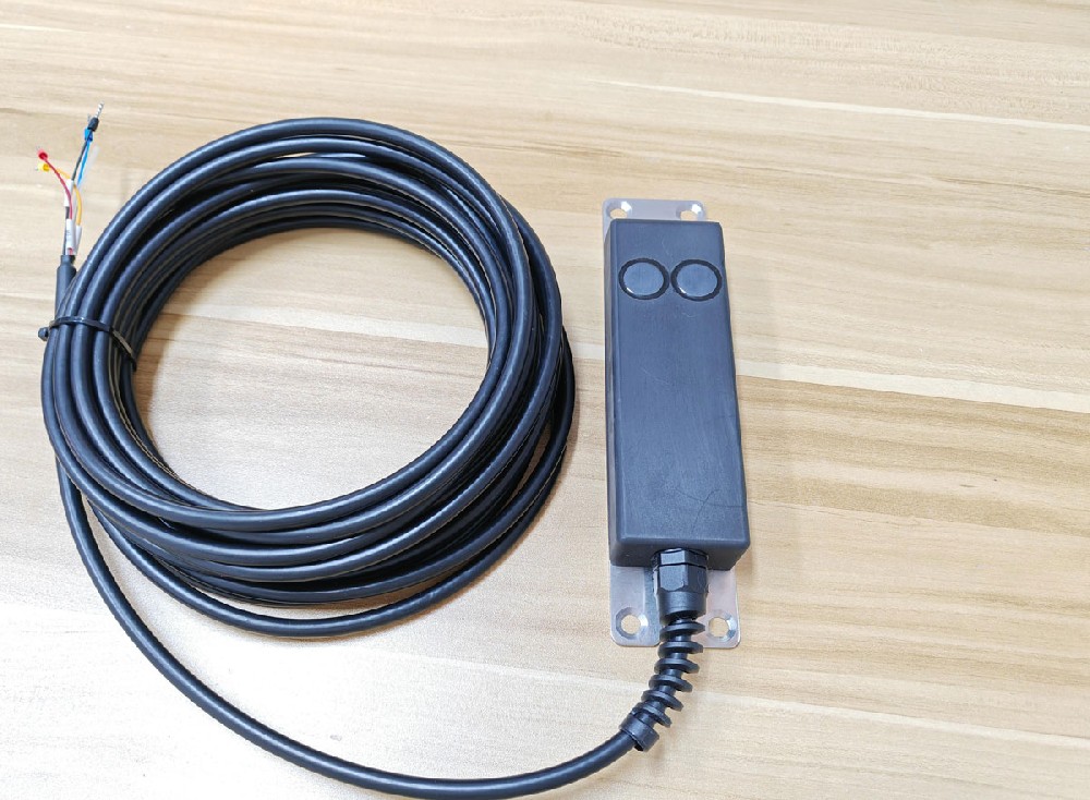
NiuBoL's non-contact radar flowmeter product combines surface-velocity radar and water-level radar and provides RS485 Modbus RTU communication. It is mounted above the water, reducing exposure to debris and sediment contact. The sensor still needs a usable water-surface echo, a representative velocity sampling zone and a secure, correctly oriented bracket. The associated cross-section model converts stage and velocity into estimated discharge.
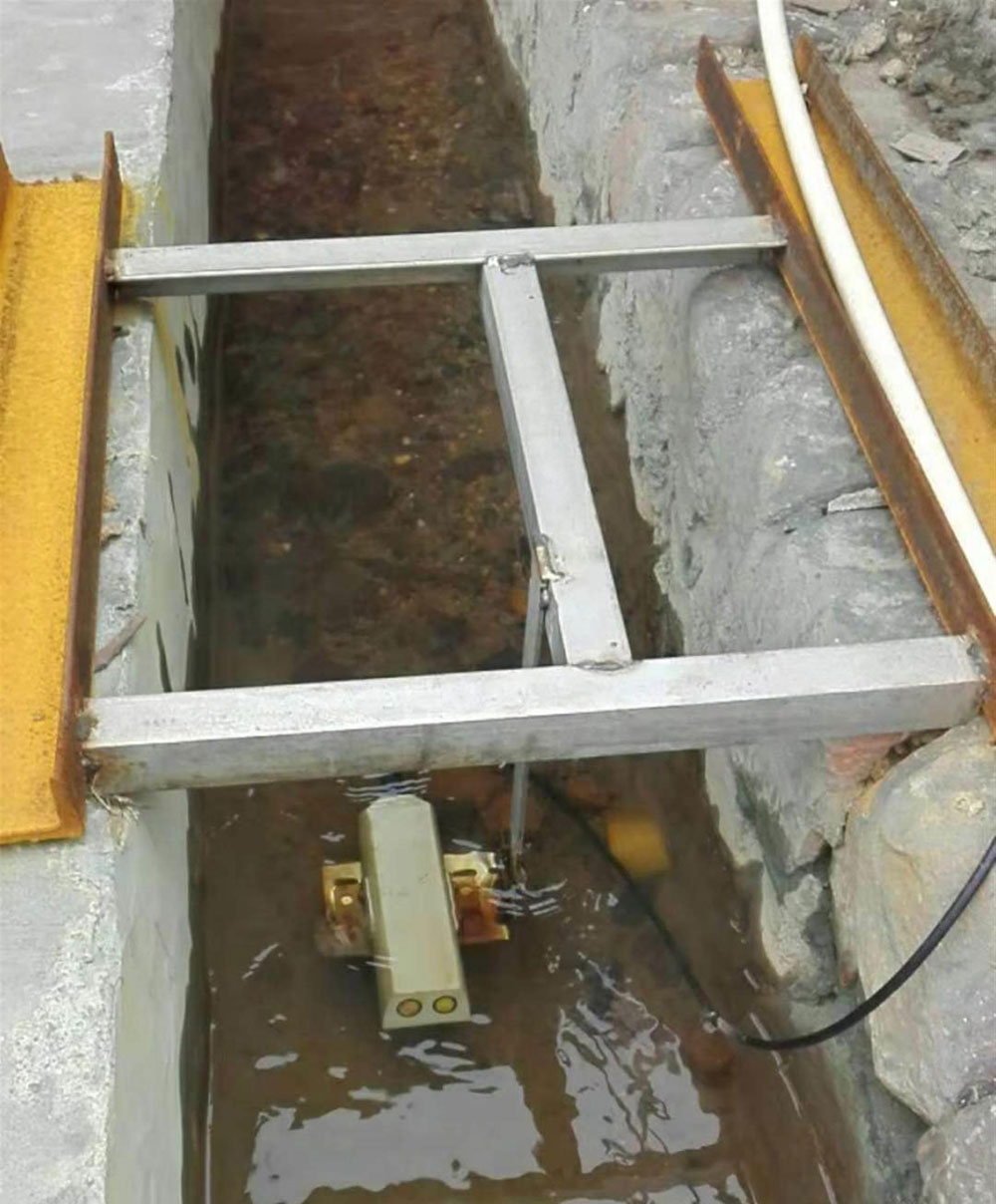
The second photograph is a submerged Doppler instrument, not the radar head in the first photograph. A Doppler velocity meter may be appropriate where a protected in-water measurement point or non-full pipe geometry is available and surface radar is unsuitable. It brings different mounting, fouling, access and cable risks. Neither method should be priced solely by the sensor head: safe installation, reference checks and ongoing cross-section maintenance are part of the measurement system.
| Site condition | Radar approach | Submerged Doppler approach |
|---|---|---|
| Floating debris or heavy sediment | Head remains above water; bracket and beam still need inspection | Protect and service the in-water head and cable |
| Weak or irregular surface signal | Test echo and velocity measurement at low flow | Assess in-water velocity profile and installation point |
| Changing cross-section | Update the stage-area and velocity conversion | Update geometry and any conversion used by the meter |
| Access during operation | Service from a safe overhead position if designed | Plan retrieval, isolation or safe in-water access |
Flow in cubic metres per second is not a directly sensed number in the same way as water level. The system combines level, a geometric area model and a velocity estimate or distribution. Retain the measured stage and velocity with their timestamps and quality flags alongside the calculated discharge. When the channel is altered by maintenance, scour or sediment, the calculation may need a revised section survey. A software update that changes a coefficient should be logged as carefully as a sensor replacement.
At very low flow, a surface radar may lose reliable velocity information even while the level radar still reports distance. This is critical if the compliance threshold is near that low-flow condition. Test the method at the minimum operating regime, not only when the station is releasing substantial water. Where a flow path runs through a closed pipe or submerged culvert, an overhead surface radar may not observe it at all; specify a suitable alternate metering method.
A calculated area is a function of stage and the surveyed channel shape. For a rectangular channel this may be simple, but an irregular natural section requires a stage-area table or another agreed geometry model. Confirm how the software interpolates between surveyed points and what it does when level falls outside the defined table. If banks scour or sediment accumulates, the same stage may correspond to a different wetted area. A scheduled re-survey may therefore be more important to discharge accuracy than a more expensive velocity head.
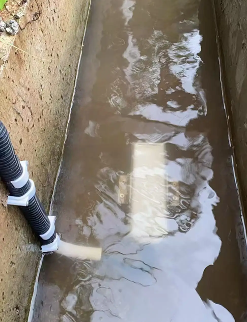
The in-channel photograph shows how a submerged sensor occupies a different physical measurement point. Its reading must not be combined with the radar's level or velocity unless the acquisition design and flow calculation explicitly allow it. For a multi-sensor station, label each point with its position, depth or beam footprint.

Write a point list covering sensor model, supply, output, RS485 address where applicable, register, scale, unit, sample interval and fault code. The NiuBoL radar flowmeter product page lists a Modbus RTU interface; a local RTU or data logger must poll it and send time-stamped records onward. A Doppler alternative may have a different interface. Check the exact ordered variant rather than assuming that all products on the same pole share one protocol.
Define how the RTU handles loss of power, a disconnected sensor, implausible stage and a failed remote link. Stale data must be marked as such. If the owner requires local buffering, retransmission, image capture or reporting to multiple platforms, specify and test those functions on the selected gateway and application. They are not automatic capabilities of the radar or Doppler sensing head. The authority's file format, timezone, station identifier and secure access should be agreed before commissioning.
For remote sites, calculate solar and battery requirements from the complete load, including the modem and any camera. State who supplies the SIM or network service and who maintains the enclosure. A sensor's nominal power figure cannot establish the endurance of the complete node. The installed photograph illustrates a solar-powered channel station, but its panel size does not define the requirements of a hydropower tailwater site.
Commission at several feasible operating conditions. Check the level datum against a surveyed reference or staff gauge, inspect the radar beam and cross-section geometry, and compare velocity or discharge with a suitable independent field method. Document the reference method and its uncertainty. A single dry-weather point is not enough to establish a conversion for a channel whose wetted shape or flow distribution changes substantially with release.
Run a controlled communication fault and verify the platform reports invalid or stale data rather than substituting zero discharge. Compare raw stage, raw velocity and calculated flow at the field RTU and the receiving system. Check accumulated volume by integrating a known interval of valid flow records; do not treat a counter as proof that the underlying instantaneous values are correct. Keep drawings, coefficients, firmware or configuration version, calibration records and test personnel in the handover file.
The last submerged Doppler photograph is a reminder that a measurement alternative may need periodic retrieval. If the project chooses that method, the service plan must include safe access and a record of fouling or repositioning. If radar is chosen, inspect bracket movement and the beam path after floods and channel works. Neither instrument is maintenance-free at the system level.
It observes surface velocity and level. The system estimates discharge from those readings and a section model or conversion. The cross-section and coefficient need site validation.
Only if the approved compliance section receives and represents all relevant flow. Map bypasses, turbine outlets and spillways before selecting one or several monitoring points.
It may suit a protected in-water position, a geometry that overhead radar cannot observe, or a site where surface velocity is not representative. It requires a practical retrieval and fouling-control plan.
Check the radar velocity sensor's minimum usable condition at the compliance flow. A valid level alone does not establish a valid discharge value; another method may be needed near low flow.
No. RS485 Modbus RTU is a local instrument interface. The RTU, network, data format, authentication and receiving platform are separate ordered and tested scope.
Include the approved section location, survey, stage datum, raw and calculated data, field comparison, conversion settings, fault tests and communications record. These allow a later reviewer to reconstruct the reported discharge.
Supply section drawings, minimum and maximum flows, tailwater behavior, release paths, access constraints, power and network availability, data-delivery specification and required acceptance method. Ask for sensor, installation and validation costs separately.
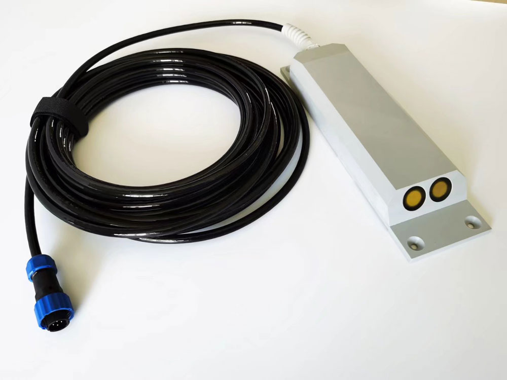
A hydropower ecological flow monitor is credible when its measurement section, method and calculation are documented and tested across the required operating range. NiuBoL radar and Doppler products offer different ways to acquire the field data. The project must still establish geometry, conversion, fault handling and an auditable report before relying on the result.
Prev:Hydropower Ecological Discharge Monitoring: Low-Flow Verification
Next:Ultrasonic Weather Station Heating: Winter Power and Valid Data
Related recommendations
Sensors & Weather Stations Catalog
 Agriculture Sensors and Weather Stations Catalog-NiuBoL.pdf
Weather Stations Catalog-NiuBoL.pdf
Agriculture Sensors Catalog-NiuBoL.pdf
Water Quality Sensor Catalog-NiuBoL.pdf
Related products
 Combined air temperature and relative humidity sensor
 TDR Soil Moisture & Temperature Sensor for irrigation| RS485 |4-20mA| NBL-S-THR
 Soil pH sensor RS485 soil Testing instrument soil ph meter for agriculture |NBL-S-PH
 Wind Speed sensor Output Modbus/RS485/Analog/0-5V/4-20mA
 Tipping bucket rain gauge for weather monitoring auto rainfall sensor RS485/Outdoor/stainless steel
 Pyranometer Solar Radiation Sensor 4-20mA/RS485


Screenshot, WhatsApp to identify the QR code
WhatsApp number:+8615367865107
(Click on WhatsApp to copy and add friends)

