





— Blogs —
—Products—
 Consumer hotline +8618073152920
WhatsApp:+8615367865107
Address:Room 102, District D, Houhu Industrial Park, Yuelu District, Changsha City, Hunan Province, China
Product knowledge
Time:2026-03-03 13:54:21 Popularity:560
A dust monitoring system can report a particle increase when dry material becomes airborne, but spray, fog, high humidity or a compromised sampling path can also affect an optical reading. Before using the result to operate dust-suppression equipment, establish what air reaches the sensor and whether the instrument is operating within its specified conditions. A working display does not prove a valid sample.
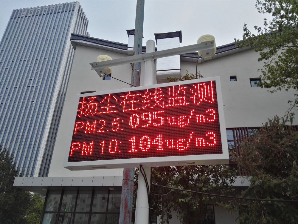
A laser-scattering sensor estimates particle concentration from the light scattered by the sampled aerosol. Its response depends on the particles entering the optical region and the instrument's processing. A blocked inlet, damaged fan, water ingress or contamination can change the result even when communications remain healthy.
Identify the inlet and outlet on the actual supplied assembly. A station photograph may show weather channels, a cabinet and a display without revealing the air path. Do not place the sensor inside an unventilated protective box, cover the inlet with an improvised fine filter or add a long sampling tube without assessing the resulting sampling behaviour.
Some instruments use a correction algorithm; others include a controlled inlet heater or dryer. These are different arrangements. A digital humidity channel does not prove that the sampled air is dried, and a heater in the electronics cabinet does not establish that particles reach the measuring region under controlled conditions.
Request the specific inlet-conditioning design when it is required by the project. Check its effect on power demand, response and the reported quantity. Do not assume that a standard low-power PM module includes automatic dehumidification simply because it can be integrated with a temperature and humidity sensor.
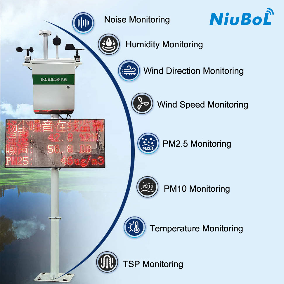
The EPA's air-sensor guidance identifies humidity and temperature as possible sources of measurement error. The practical response is to retain those environmental observations and review the affected intervals, not to delete every high reading during damp weather. Real dust and moisture-related effects can occur together.
PM2.5, PM10 and total suspended particulates, TSP, are different measurement quantities. A PM10 output is not a TSP channel with another label. If a project needs TSP, specify an appropriate instrument and sampling arrangement rather than deriving it by multiplying a PM10 reading or relabelling the larger numerical range.
The NiuBoL particulate matter sensor configuration below provides separate PM2.5 and PM10 ranges. These parameters belong to that configuration; they are not a single universal specification for every dust station pictured in a project proposal.
| PM sensor item | Configuration parameter | Field implication |
|---|---|---|
| PM2.5 range | 0-1000 micrograms/m3 | Do not apply the PM10 span to this channel |
| PM10 range | 0-2000 micrograms/m3 | Not a specification for TSP |
| Error statement | ±15% and ±10 micrograms/m3 maximum error, with 25 C and 50%RH test conditions | Obtain the applicable acceptance envelope; do not treat the notation as an unrestricted field guarantee |
| Supply and consumption | 12-24 VDC; up to 350 mW | Excludes any additional conditioning equipment, gateway and display |
| Digital interface | RS485 Modbus RTU | Verify the actual map, scales and fault information |
| Operating environment | -20 to 60 C; 0-99%RH, non-condensing | A high humidity limit does not permit liquid water at the inlet |
| Standard lead | 2.5 m | Specify extensions, jacket material and protected entries for the installation |
A monitor immediately inside a fog-cannon plume may sample droplets and a locally altered aerosol rather than the air condition the project intends to track. Moving the inlet to suit the measurement objective is preferable to increasing an alarm threshold until the system stops reacting to its own spray.
During commissioning, record the suppression operating state, wind and humidity alongside PM observations. Compare periods before, during and after normal operation. Do not generate hazardous dust or intentionally wet an inlet to perform a test. Use ordinary site activity and a controlled equipment test plan.
Three common outcomes need different responses. A short rise that follows the moving spray plume needs an exposure review. A persistent change after a wetting event needs an inlet and contamination inspection. A rise that coincides with dry material handling may represent a real event, but the sensor alone does not identify the material or prove which activity caused it.
Do not blow compressed air through the optical chamber or introduce cleaning liquid unless that procedure is approved for the device. Cleaning a screen, servicing a pump on a pump-equipped system and cleaning internal optics are not interchangeable tasks. Keep maintenance observations with the data so a step change after service can be interpreted.
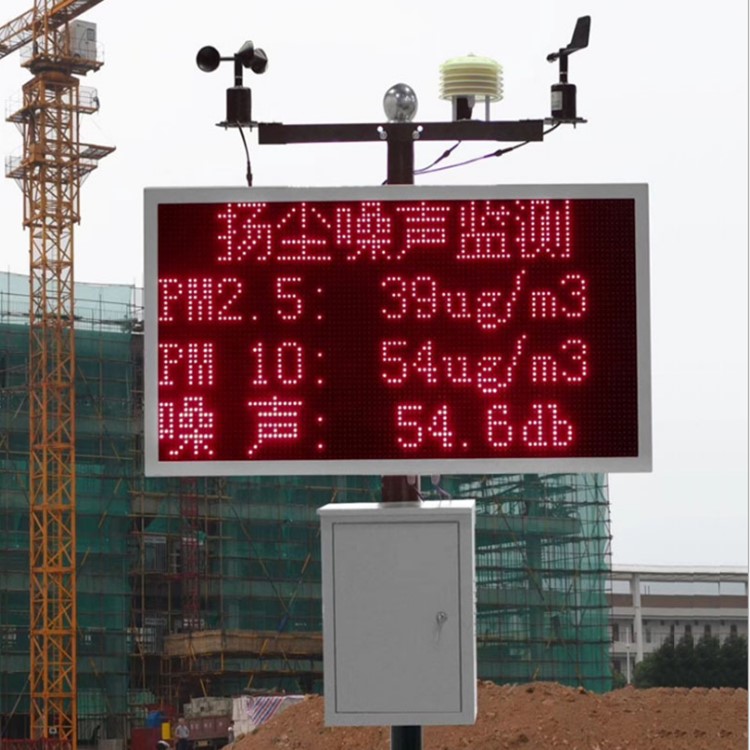
The sensor supplies measurements; a logger, RTU or PLC implements the chosen alarm or control logic. Confirm normal readings, over-range behaviour, missing replies and recovery after a restart. A communications fault must not be silently converted to a measured zero or a continuously repeated last value.
Then test the suppression controller through its approved test mode. Check the requested output, actual equipment response and the conditions that prevent operation. The PM threshold, delay and reset rules must suit the operating purpose; avoid a feedback cycle in which spray raises the reading and the raised reading extends the spray indefinitely.
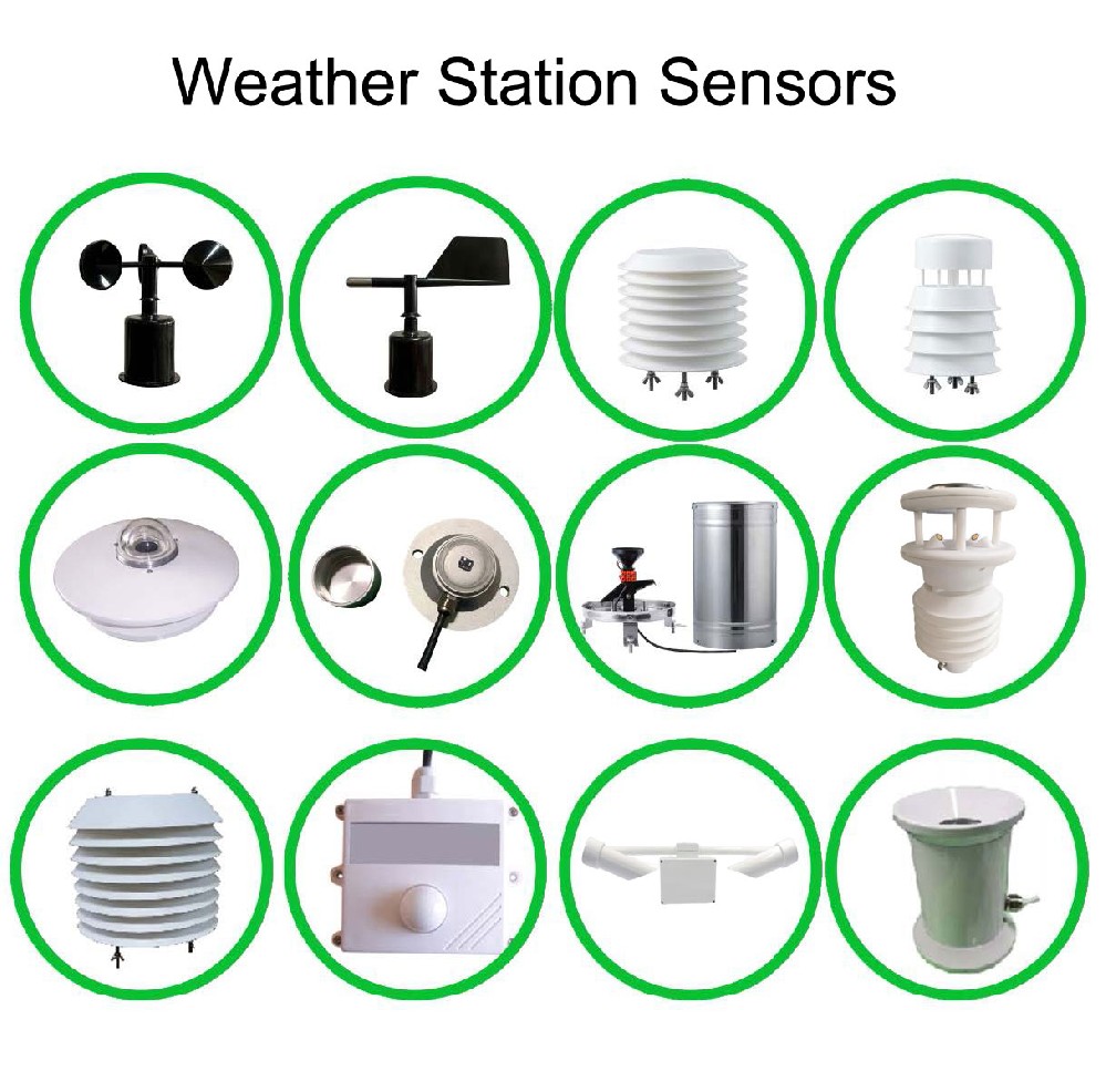
If noise and weather channels are added, qualify them separately. NiuBoL NBL-W-SS and NBL-W-DS wind instruments have IP65 protection, but that does not establish the PM inlet's resistance to direct spray. Nor does a wind direction record uniquely locate an emission source. Keep those limits visible in the system design.
For construction works, state the expected dust-generating activities and available servicing access. For a stockpile or transfer point, describe the material, nearby spray equipment and whether the requirement concerns local operational trends or another specified measurement purpose. A demolition project may need a changing layout rather than a permanent pole at the entrance.
Separate the instrument, inlet conditioning if required, power, communications, display, controller interface and comparison testing. Ask NiuBoL for the available PM configuration and protocol information. Do not compare a bare sensor with an installed station, or assume a low headline price includes a dryer, pump or suppression controller.
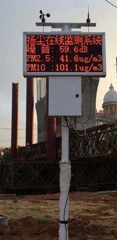
Do not assume so. Confirm whether the quoted configuration includes physical conditioning, an algorithm or neither. A humidity sensor and a PM sensor in the same station do not establish a controlled dry sample path.
Only if the project requirement is changed to the appropriate quantity by the responsible project team. They are not interchangeable labels. A sensor's PM10 range does not prove TSP measurement, and there is no universal conversion between the two for every site aerosol.
No. Mark and investigate the affected periods using humidity, spray operation and instrument condition. A high value can include a real particle event as well as moisture influence. Automatic deletion can erase the evidence needed to understand what occurred.
Check timestamps, local acquisition and device diagnostics before assuming constant clean air. Verify the sampling path and power as well as the data link. Successful Modbus communication does not prove that air is moving through the measuring region.
Only through a suitable controller design with the required operating permissions, timing and fault response. Review the monitor's exposure to spray and test the complete loop. Environmental trend measurement alone does not establish a safe automatic equipment-control arrangement.
Send the required particle fractions, concentration expectations, site photographs, spray arrangement, power availability and receiving platform. Identify any required inlet conditioning or comparison testing. These details allow a quotation based on the sampling task rather than a generic pole-and-display package.
A useful dust record depends on a suitable aerosol sample, not just a functioning communications link. Specify the particle fraction, keep spray influence under review and inspect the inlet before altering calibration. Test measurement validity and suppression control as separate tasks, then connect them only through a defined operating design.
Prev:Campus Meteorological Station Procurement: Compare Hardware and Software Scope
Next:Small Water Quality Monitoring Buoy: Test the Loaded Assembly Before Launch
Related recommendations
Sensors & Weather Stations Catalog
 Agriculture Sensors and Weather Stations Catalog-NiuBoL.pdf
Weather Stations Catalog-NiuBoL.pdf
Agriculture Sensors Catalog-NiuBoL.pdf
Water Quality Sensor Catalog-NiuBoL.pdf
Related products
 Combined air temperature and relative humidity sensor
 TDR Soil Moisture & Temperature Sensor for irrigation| RS485 |4-20mA| NBL-S-THR
 Soil pH sensor RS485 soil Testing instrument soil ph meter for agriculture |NBL-S-PH
 Wind Speed sensor Output Modbus/RS485/Analog/0-5V/4-20mA
 Tipping bucket rain gauge for weather monitoring auto rainfall sensor RS485/Outdoor/stainless steel
 Pyranometer Solar Radiation Sensor 4-20mA/RS485


Screenshot, WhatsApp to identify the QR code
WhatsApp number:+8615367865107
(Click on WhatsApp to copy and add friends)

