





— Blogs —
—Products—
 Consumer hotline +8618073152920
WhatsApp:+8615367865107
Address:Room 102, District D, Houhu Industrial Park, Yuelu District, Changsha City, Hunan Province, China
Product knowledge
Time:2026-03-06 17:35:28 Popularity:741
An automatic soil moisture monitoring system does not come with one irrigation threshold suitable for every field. A reading expressed as volumetric water content is not the same as a percentage of field capacity or the proportion of available water remaining. Before using a NiuBoL soil profile to generate an irrigation request, agree the soil-water basis, relevant root depth and uncertainty around the decision.
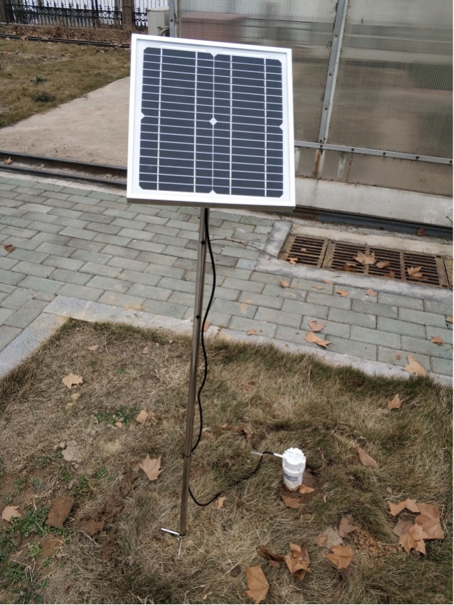
A sensor reading of 24% VWC means an estimated volumetric water content of 0.24 m3/m3. It does not mean that the soil contains 24% of its available water. Field capacity and wilting point describe different reference conditions; the distance between them determines an estimate of plant-available storage for a specified layer.
This matters when a tender requests an alert at 60% of field capacity. That phrase is not equivalent to 60% depletion of available water. A control programmer cannot choose between those interpretations without changing the agronomic meaning. Write the intended calculation explicitly before commissioning a threshold.
| Term | Meaning | What must be supplied |
|---|---|---|
| Volumetric water content | Water volume divided by bulk soil volume | Sensor output, units and appropriate field interpretation |
| Field capacity | A soil-water reference after drainage has substantially slowed | Representative determination for the soil and layer |
| Available water storage | Storage between field capacity and wilting point | Both reference contents and the represented thickness |
| Root-zone depletion | Water deficit relative to field capacity over a defined root zone | Layer values, thicknesses and an appropriate root-zone model |
| Irrigation trigger | A management decision criterion | Crop, stage, rooting conditions and an agreed strategy |
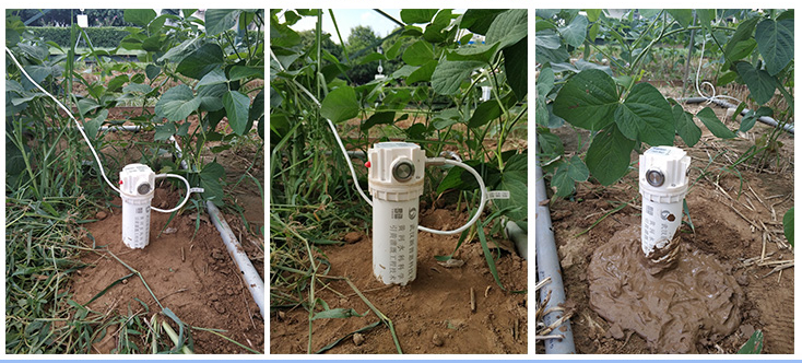
Assume, only for illustration, a uniform 0.40 m root zone with field capacity 0.30 m3/m3 and wilting point 0.15 m3/m3. Estimated total available water is 1,000 x (0.30 - 0.15) x 0.40 = 60 mm. If current representative content is 0.24 m3/m3, depletion relative to field capacity is 24 mm, or 40% of that available storage.
In the same example, 60% of field capacity is 0.18 m3/m3. That corresponds to 48 mm depletion, or 80% of available storage, not 60%. A trigger at 60% depletion would instead correspond to 0.21 m3/m3. The arithmetic shows why an unclear percentage can produce substantially different operating instructions.
FAO's soil-water stress guidance distinguishes total available water and readily available water using soil properties, rooting depth and a crop-dependent depletion fraction. Use those concepts to agree the decision basis; the illustrative soil values above are not a crop recommendation or site calibration.
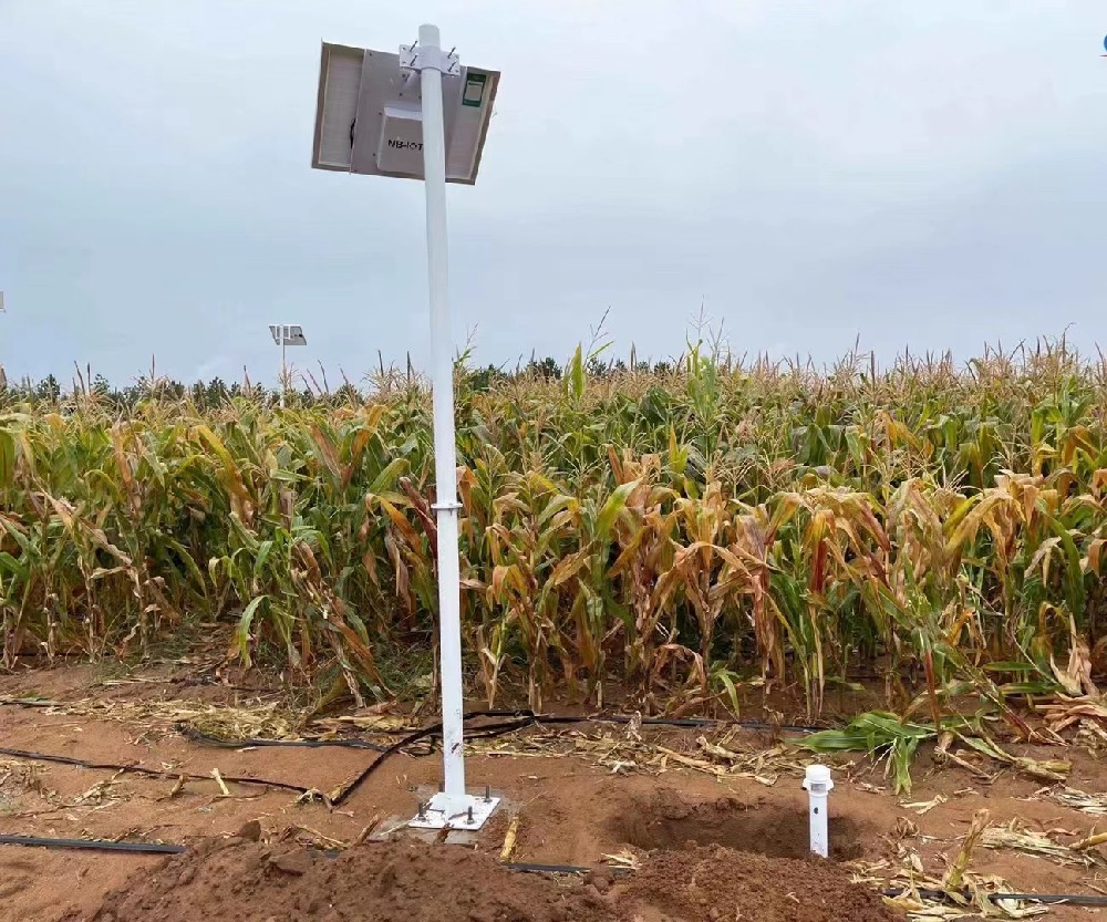
The NBL-S-TMSMS tubular multi-depth sensor measures moisture and temperature at selected depths using FDR. Its tube must be coupled appropriately to the surrounding soil. Electrical insulation between an electrode and the soil does not make the installation independent of air gaps, disturbed backfill or the wetting pattern around the tube.
| NBL-S-TMSMS item | Specification or configuration | Decision consequence |
|---|---|---|
| Standard depth positions | 10, 20, 30 and 40 cm; other configurations subject to selection | Verify that the ordered positions cover the relevant root zone |
| Moisture output | Volumetric water content; 0.1% resolution; stated laboratory accuracy +/-3%, field accuracy +/-5% | Do not treat a small display increment as field accuracy |
| Temperature | -40 to 80 C; +/-0.5 C; 0.1 C resolution | Temperature is a separate layer measurement, not an EC or salinity channel |
| Supply and digital interface | 12-24 VDC adapter configuration; RS485 Modbus RTU | Match the ordered power arrangement and register map |
| Protection | IP67 above ground; IP68 below ground | Protect the exposed connection arrangement and follow immersion conditions |
| Tube construction | PVC tube with epoxy sealing | Check installation and service constraints for the site |
Obtain power consumption and cable details for the supplied revision before sizing the station. Sensor, logger and modem loads are separate. A solar panel rating or a sleep-current figure from another revision cannot establish continuous operation for the complete automatic soil moisture monitoring system.
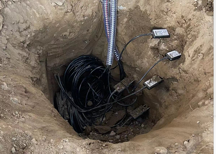
A sensor at 20 cm observes a local sensing volume, not every cubic centimetre from the surface to 20 cm. Converting a profile into millimetres of water requires an agreed thickness represented by each observation. For a layered approximation, calculate each layer's deficit as 1,000 x (field-capacity content minus current content) x layer thickness in metres, then combine appropriate layers.
Do not simply average all depths if they represent different thicknesses or different soils. Nor should a deep wet layer automatically cancel a shallow dry condition for a newly established shallow-rooted crop. Record the rooting assumption and review it as the crop develops. A deep response after irrigation indicates water movement near that sensor; it does not by itself quantify groundwater recharge or nutrient leaching.
In drip irrigation, placement relative to emitters changes the response. Before using a threshold, observe at least a representative wetting and drying sequence and compare it with field checks. If the wetting bulb misses the sensor, changing the alarm value is not a sound substitute for reviewing whether the location represents the intended management zone.
A narrow on/off band can make a controller react repeatedly to normal variation, installation effects or uncertainty. Review the proposed band against the instrument's field performance and the farm's irrigation response. Persistence time, separate start and stop criteria and a maximum operating limit may be appropriate, but their settings belong to the engineered irrigation strategy.
Test a missing, implausible and stale moisture reading before permitting automatic operation. The controller should not interpret a disconnected probe as dry soil and open a valve indefinitely. The soil system provides observations; valve feedback, flow confirmation and independent operating limits remain separate requirements if the project includes control.
Start with supervised recommendations where the soil references and installation behaviour are still being established. Record irrigation timing and applied water alongside the moisture profile. This provides a basis for refining the decision and distinguishes an incorrect threshold from a blocked emitter, changed pressure or a sensor that is not in the wetted volume.
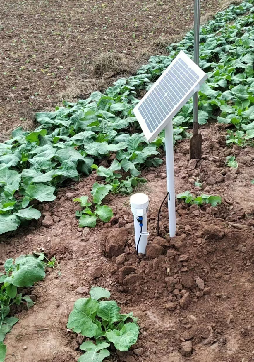
Send NiuBoL the crop and growth stage, soil layers, desired depths, irrigation method and intended receiving system. Identify whether the deliverable is a measurement station, an advisory output or a controller interface. Include who determines field capacity, wilting point and the permitted depletion; these are not automatically supplied by a Modbus register.
For acceptance, verify the layer identity, unit, scaling, installation contact and response to a documented irrigation event. Separately check any conversion to storage and the rule producing a recommendation. Retain original readings and the calculation settings so an updated root-zone assumption does not silently rewrite the meaning of the historical record.
No. It is also different from 60% depletion of available water. Specify the soil references, crop and calculation before applying a percentage to an automatic decision.
A moisture profile can support field investigation, but those reference properties require an appropriate determination. Do not assume every logger estimates them correctly from one irrigation event.
No. Gaps and disturbed material can alter the observed dielectric environment and water movement. Follow the installation procedure for the supplied tube and soil conditions.
Only with justified representation and weighting. Assign appropriate layer thicknesses and soil references; an unweighted average is not automatically a valid storage estimate.
Not from its moisture and temperature channels. Salinity assessment needs suitable additional measurements and interpretation. Water movement alone does not identify salt mass or nutrient loss.
Specify the sensor depths, acquisition and transmission equipment, power supply, installation and any advisory or control work. Include field characterization and acceptance checks where those are part of the project.
An automatic soil moisture monitoring system becomes a useful irrigation input when its measurements and decision thresholds share the same soil-water basis. Select a suitable NBL-S-TMSMS depth configuration, establish representative field behaviour and validate any storage calculation before connecting it to automatic control. That approach gives the enquiry a clear technical scope without promising universal water savings or crop effects.
Match the selected sensor and revision before using its wiring or installation procedure. Tubular profiles and separate point probes have different placement and acquisition requirements.
 NBL-S-TMSMS-Tubular-Multi-depth-Soil-Moisture-Sensor-Instruction-Manual.pdf
NBL-S-TM-Soil-temperature-and-moisture-sensor-Instruction-Manual-4.0.pdf
NBL-S-THR-Soil-temperature-and-moisture-sensors-Instruction-Manual-V4.0.pdf
Prev:Scenic Area Weather Station: Match Visitor Displays to Measured Data
Next:Agricultural Weather Station: Observations, Forecasts and Crop Predictions
Related recommendations
Sensors & Weather Stations Catalog
Agriculture Sensors and Weather Stations Catalog-NiuBoL.pdf
Weather Stations Catalog-NiuBoL.pdf
Agriculture Sensors Catalog-NiuBoL.pdf
Water Quality Sensor Catalog-NiuBoL.pdf
Related products
 Combined air temperature and relative humidity sensor
 TDR Soil Moisture & Temperature Sensor for irrigation| RS485 |4-20mA| NBL-S-THR
 Soil pH sensor RS485 soil Testing instrument soil ph meter for agriculture |NBL-S-PH
 Wind Speed sensor Output Modbus/RS485/Analog/0-5V/4-20mA
 Tipping bucket rain gauge for weather monitoring auto rainfall sensor RS485/Outdoor/stainless steel
 Pyranometer Solar Radiation Sensor 4-20mA/RS485


Screenshot, WhatsApp to identify the QR code
WhatsApp number:+8615367865107
(Click on WhatsApp to copy and add friends)

