





— Blogs —
—Products—
 Consumer hotline +8618073152920
WhatsApp:+8615367865107
Address:Room 102, District D, Houhu Industrial Park, Yuelu District, Changsha City, Hunan Province, China
Product knowledge
Time:2021-12-27 20:49:03 Popularity:2239
Quick answer: An industrial IoT gateway connects field devices to a local or remote data system. It may poll RS485 Modbus sensors, translate data to an upstream protocol, buffer records during a network outage and forward them through Ethernet or cellular service. Compatibility must be checked at both sides; the word "gateway" alone does not guarantee that it can read every PLC or cloud platform.

For a system integrator, an industrial IoT gateway is often the point where an otherwise working instrument becomes a usable application tag, or an unusable stream of numbers. Receiving a response on RS485 proves only part of the connection. The value must still have the correct channel identity, scale, unit and time before it can be compared with an alarm or stored in a customer's monitoring system.
At the field side, a gateway may act as a Modbus RTU master and collect registers from sensors, meters or an RTU. At the upstream side, it can expose data through a supported interface such as Modbus TCP, MQTT or HTTP. Some projects use a separate data logger for sampling and storage, with the gateway used only for backhaul. Others combine these functions in one device.
Define those roles on a connection drawing before choosing hardware. If a PLC already polls a serial bus, do not add another independent Modbus RTU master to that same bus and expect both to operate correctly. Obtain the data through an agreed PLC interface or use a separate acquisition arrangement. A gateway acting as a serial master is different from one merely carrying a transparent serial session across a network.
| Arrangement | Role that must be supplied | Common scope mistake |
|---|---|---|
| RS485 instruments to an MQTT receiver | Local polling, register decoding and application message creation | Buying a serial transport device without the required polling and payload functions. |
| Existing PLC to remote SCADA | Supported PLC-side access and an agreed upstream client/server arrangement | Assuming every gateway includes a driver for every PLC. |
| Serial instrument accessed through Ethernet | Transparent transport or actual Modbus RTU/TCP conversion, as required | Treating a virtual serial connection as a Modbus TCP server. |
| Separate logger and cellular router | The logger acquires records; the router carries their network traffic | Expecting a router alone to create sensor tags and historical records. |
A NiuBoL industrial cellular router and a sensor data collector therefore solve different parts of a project. Some devices combine functions, but the ordered firmware and interfaces still decide what is available. Request a demonstration of the actual path required by the customer rather than accepting a list of protocol names as proof that the integration is complete.
RS485 is the physical link. Modbus RTU is one protocol commonly carried over it. The gateway needs the correct device address, baud rate, parity, function code and register map. A multi-device bus should use unique addresses and a suitable cable topology. The project should also calculate the power demand of field sensors instead of assuming that the gateway powers every device.
For each required point, record device identity, register address, read function, number format, scale, unit and invalid-value handling. Agree how the configuration tool represents addresses: a display such as 40001 may be a reference convention rather than the address bytes sent to the device. Likewise, adjacent 16-bit registers do not automatically contain the same type of 32-bit value. Verify the mapping against the instrument, not a visually similar driver.
Start with one known read-only point and compare its decoded result with an independent local indication where available. Then check the remaining types, including a signed temperature or a status field if the device provides them. Do not write configuration registers merely to prove that communication works.
For an analog transmitter, the gateway or logger needs the appropriate current or voltage input, not simply an RS485 terminal. Confirm the input range, sensor supply arrangement and conversion to engineering units. A 12-bit or 16-bit ADC designation describes conversion resolution, not the accuracy of the connected pressure or water-quality sensor. Include the transmitter and input errors when deciding whether the full measurement chain meets the project requirement.
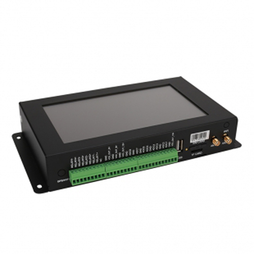
The TG462 / TG462S family is one NiuBoL acquisition option for mixed interfaces. Its physical inputs can reduce the need for separate conversion devices, but channel count must be considered alongside polling behavior and firmware functions. The TG462S adds a local touchscreen. Neither a display nor a programmable operating system removes the need to configure the customer's tags and communications.
| TG462 / TG462S characteristic | Technical detail | Check for the installation |
|---|---|---|
| Serial ports | 3 RS485 and 4 RS232, including one debug port | Allocate working interfaces; keep the debug port out of the normal field-port count. |
| Analog acquisition | Eight 12-bit ADC inputs; 4-20 mA default, 0-5 V optional | Confirm the input version and scaling for each transmitter. |
| Digital I/O | Four digital inputs and four relay outputs | Verify electrical limits and the actual counting or control function required. |
| Ethernet / power | Two 10/100 Mbit/s ports; 5-35 V DC input | Check LAN/WAN assignment and supply loading during communication. |
| Current at 12 V | Acquisition 251-357 mA; communication 305-412 mA | Budget attached sensors and other devices separately. |
| Operating environment | -35 to +75 degrees C; IP30 housing | Provide the appropriate cabinet for outdoor or wet locations. |
| Communication example | 4G LTE Cat 4 regional module options; Modbus RTU/TCP gateway and MQTT functions | Confirm module, firmware and receiver configuration; do not infer arbitrary platform compatibility. |
Evaluate the bus under a slow or missing-device condition. In an illustrative timing case, 12 unavailable instruments with a two-second timeout can consume about 24 seconds before retries or other work. That is not a TG462 performance figure; it shows why an assumed one-second update cycle can fail even when normal responses are quick. Agree polling groups, timeouts and a policy for unavailable instruments, then test the busiest expected configuration.
For MQTT or HTTP delivery, define the data schema, topic or endpoint, authentication, retry method and timestamp source. For a PLC or SCADA connection, document register or tag mapping and who acts as client and server. Test a known field value through the complete path before adding all points.
A Modbus TCP client requesting values and an MQTT application receiving published messages have different roles. The upstream design should identify who initiates each connection, which values are exposed or published and how the receiver identifies a device. If a transparent serial tunnel is selected, the remote application may still need to create and interpret the serial protocol. Successful IP connectivity does not resolve that work.
For a cellular installation, the selected modem, regional service and antenna arrangement must be compatible. A router can provide the connection while a separate logger supplies the records. Confirm who supplies and manages the SIM and the receiving account. These decisions affect the offered service and commissioning work; they should not be left until the field team discovers that a visible signal indicator is not a working application connection.

Keep local control requirements distinct from remote monitoring. An alert received by a web application is not a protective interlock. Where the project includes remote commands, define authorization, command expiry, local permissives and confirmation of execution. Do not enable writes to a production controller as a casual connectivity test. The plant's approved operating procedure governs any such commissioning work.
If no instrument responds, investigate power, bus wiring and serial settings before changing application calculations. If just one device fails, check its address, configuration and branch connection. If decoded values are correct locally but wrong remotely, inspect the point map, scale and receiver schema. If values remain plausible but stop changing, inspect acquisition timestamps and quality status before assuming the process has become steady.
For intermittent problems, compare communication errors with polling load, equipment operation and supply conditions. Keep error and restart records with their times so a maintenance visit can investigate a pattern rather than a single screen capture. A gateway restart that temporarily restores communication is a symptom, not proof that the sensor or software has been permanently corrected.
For a NiuBoL compatibility review, send the instrument list, protocol details, required points and update intervals, plus the receiving system's interface requirements. State the power and enclosure conditions, storage and recovery expectations, and whether existing PLC control must remain untouched. This lets the quotation distinguish hardware, configuration and application work instead of presenting a bare gateway price as the cost of the whole integration.
No. RS485 describes the electrical link, not a universal data format. The device must use a supported protocol and its settings and point map must be configured correctly. Check non-Modbus or proprietary instruments individually.
Do not attach a second independent Modbus RTU master to the same bus without a specifically designed coordination arrangement. Obtain data through the PLC or provide a separate compatible path. Confirm the protocol roles before wiring.
A response can be valid while the register, function, byte interpretation, scale or unit is wrong. Compare a known point through each stage and verify the map. Do not calibrate the physical sensor to compensate for an application-decoding error.
No. The receiver may require particular topics, payload fields, authentication and device provisioning. Confirm those requirements and demonstrate a complete exchange using the ordered configuration. MQTT support does not include every customer's application integration.
A router may carry network traffic but need not poll instruments, decode registers or create historical records. It can be sufficient when another device already supplies those functions. Otherwise select an acquisition device or confirm that the chosen combined unit performs them.
Run a controlled interruption, then inspect acquisition times, recovered records, gaps and duplicates after reconnection. Include a storage-limit condition where relevant. Agree the overwrite and retry behavior for the actual software instead of inferring it from storage size.
Compare working interfaces, supported protocol roles, point count and polling requirements, enclosure and power, storage behavior and integration services. Separate recurring connection services from hardware. Require the same customer-side delivery format and acceptance test in each scope.
Gateway selection is an interface-matching exercise. Field protocol, data model, network path and failure behavior must all be specified.
Prove one complete measurement path before expanding the installation. An industrial IoT gateway is useful when the receiver gets an identifiable, correctly interpreted and time-qualified value, with fault behavior that the operating team has actually tested.
Related recommendations
Sensors & Weather Stations Catalog
 Agriculture Sensors and Weather Stations Catalog-NiuBoL.pdf
Weather Stations Catalog-NiuBoL.pdf
Agriculture Sensors Catalog-NiuBoL.pdf
Water Quality Sensor Catalog-NiuBoL.pdf
Related products
 Combined air temperature and relative humidity sensor
 TDR Soil Moisture & Temperature Sensor for irrigation| RS485 |4-20mA| NBL-S-THR
 Soil pH sensor RS485 soil Testing instrument soil ph meter for agriculture |NBL-S-PH
 Wind Speed sensor Output Modbus/RS485/Analog/0-5V/4-20mA
 Tipping bucket rain gauge for weather monitoring auto rainfall sensor RS485/Outdoor/stainless steel
 Pyranometer Solar Radiation Sensor 4-20mA/RS485


Screenshot, WhatsApp to identify the QR code
WhatsApp number:+8615367865107
(Click on WhatsApp to copy and add friends)

