





— Blogs —
—Products—
 Consumer hotline +8618073152920
WhatsApp:+8615367865107
Address:Room 102, District D, Houhu Industrial Park, Yuelu District, Changsha City, Hunan Province, China
Product knowledge
Time:2024-11-24 15:11:46 Popularity:2026
Small meteorological station installation includes removing the correct shipping restraints while retaining the parts that protect the measurement during operation. A rain bucket held for transport, a temporary pyranometer cover and a permanent temperature radiation shield require different treatment. Identify each part before assembly, check the selected sensor connections and establish the direction reference before tightening the final mounting. A successful self-test is not a calibration.
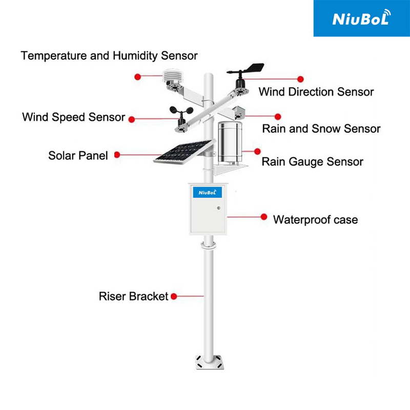
Compare the packing list with the actual sensor labels, crossarms, brackets, cables and enclosure components. Keep instrument-specific parts with their corresponding sensors. A spare mounting screw, temporary cap and permanently fitted cover may look similar in a mixed delivery. Photograph anything uncertain and obtain identification before removing or modifying it.
Check the output and supply version as well as the model name. An RS485 instrument and an analog version may have different wiring despite a similar housing. Preserve the cable labels and do not connect by colour alone across different devices. Resolve a missing adaptor or unclear connector while the equipment is accessible, not after the mast has been raised.
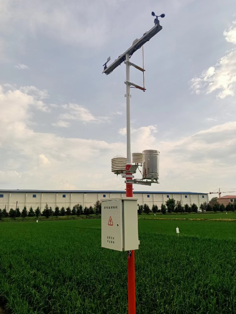
| Part or condition | Installation action | What must remain intact |
|---|---|---|
| Rain-bucket transport restraint | Remove the identified restraint using the instrument's access procedure. | Bucket geometry, calibration adjustments, wiring and operating fasteners |
| Temporary cover over a pyranometer's optical surface | Remove the temporary cover before measurement. | The glass dome and other functional optical parts |
| Louvered air-temperature radiation shield | Retain it in the intended operating arrangement with free ventilation. | Shield plates, sensing assembly and mounting geometry |
| Connector cap on an unused port | Retain the specified protection for ports that remain unused. | Seals and the enclosure's intended environmental protection |
| Cable ties on the mast | Identify whether each tie is shipping restraint or installed cable support. | Required strain relief and secure cable routing |
Do not use a general instruction to remove all covers or cut all ties. Some components prevent transport movement, while others provide operational shielding or mechanical support. If a part's purpose is unclear, its location and the instrument's assembly drawing are more useful than an assumption based on another station.
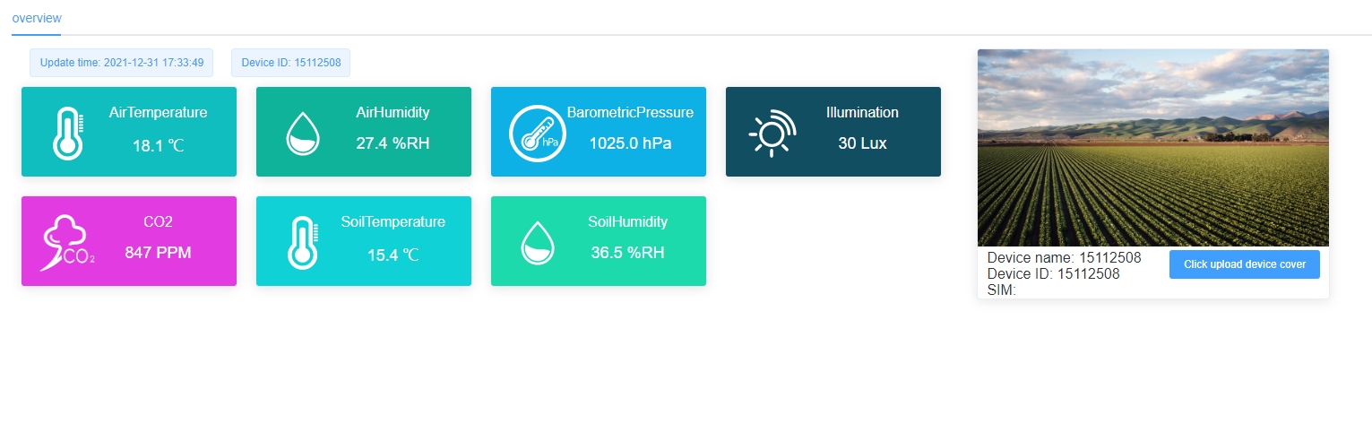
For the NBL-W-RS arrangement, access the outer barrel as specified and remove the identified bucket transport restraint. Inspect for packing material that could obstruct the funnel or movement. Reassemble the housing and retain collector level. Do not turn calibration stops to make the bucket move or disturb soldered wiring during this task.
Check a permitted response at the local acquisition input, then at the display. Distinguish a locked mechanism from a wrong input assignment. Record any generated test counts as service activity rather than natural rain. The 0.2 mm resolution version associates one tip with 0.2 mm, but a counting response alone does not establish field rainfall accuracy.
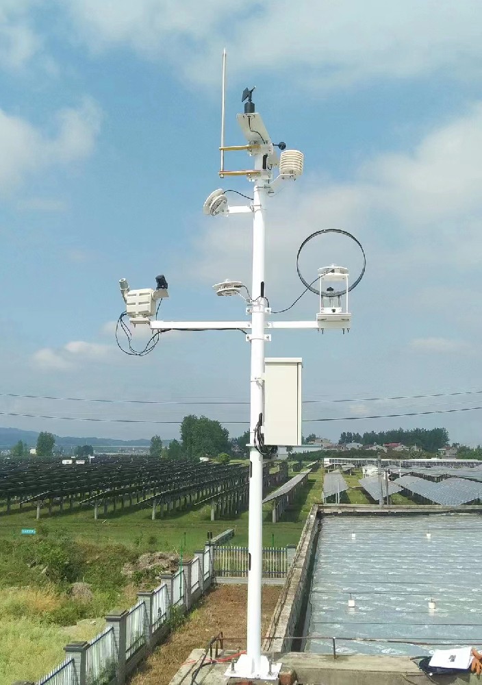
A pyranometer's temporary transport cover must not remain over the measurement surface. The glass dome is a functional part of the instrument, not disposable packaging. Check the intended plane and make sure the mast, crossarm or solar panel does not shade it. Do not compensate for a covered sensor by changing its scaling.
The air-temperature shield has the opposite purpose: it remains around the air-sensing arrangement to reduce direct radiation influence while allowing ventilation. Removing it because the sensor appears obstructed changes the measurement conditions. A newly assembled station may communicate normally while giving unsuitable temperature or irradiance readings because these two types of protection were confused.
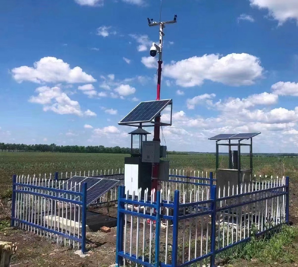
The NBL-W-DS wind vane uses a south reference mark in its mounting arrangement. Establish the required geographic reference and set that mark correctly before the bracket is finally secured. Do not transfer a north-arrow instruction from a different instrument to this vane, and check for any configured software offset before adding another correction.
Confirm that cups and vane have their required movement clearance after all neighbouring equipment is fitted. A cable, tie or newly added crossarm can obstruct movement without causing a communication error. Wind-sensor protection ratings do not remove that mechanical check; NBL-W-SS and NBL-W-DS use IP65 protection.
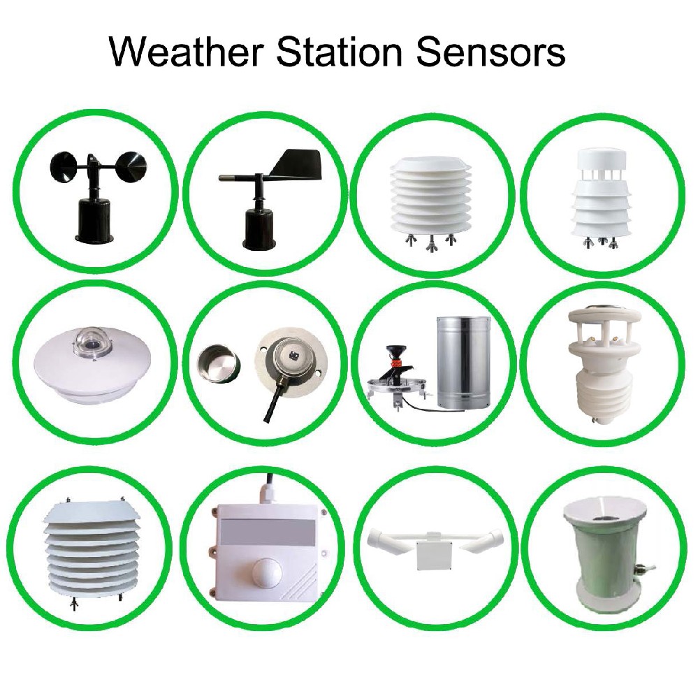
| Component example | Relevant parameter | Check before release |
|---|---|---|
| NBL-W-RS | 0.2 mm resolution; operation 0-50 C; selected switching, voltage or RS485 output | Transport restraint removed, collector level retained and correct receiving input |
| NBL-W-DS | 0-360 degrees; accuracy +/-3 degrees | South-reference mounting, free movement and correct direction field |
| NBL-W-HPRS | 0-2000 W/m2; operating temperature -40 to 50 C | Temporary cover removed, optical dome retained and intended measurement plane restored |
| NBL-W-LBTH | Air temperature -40 to 80 C; RS485 or 4-20 mA options | Correct output wiring and the intended shielded, ventilated exposure |
Complete wiring with the circuit isolated and check it before energizing. For RS485 Modbus RTU versions, verify the particular device settings and register interpretation; RS485 is not a universal protocol identifier. Keep these assembly checks separate from the foundation, structural and electrical protection work required for the actual site.
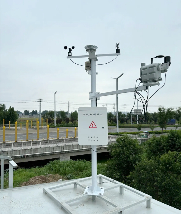
The mechanism may still be restrained, or the collection and input path may be incorrect. Check the identified transport restraint and receiving channel before changing calibration. A communication reply alone does not prove bucket movement or valid counting.
No. Remove only identified temporary protection. Retain functional radiation shields, optical domes, seals and unused-port protection in the intended arrangement. The distinction depends on the actual component, not its appearance alone.
No. The NBL-W-DS mounting reference is south; other models can use different markings. Identify the installed sensor and check both mechanical orientation and configured corrections.
No. A self-test or controlled response checks particular functions. Calibration requires an appropriate reference and procedure. Correct assembly and configuration faults at their source rather than concealing them with an offset.
Send NiuBoL the station configuration, sensor label, packing-list reference and photographs showing the part in position. Keep the part and its associated hardware intact until its purpose and installation method are identified.
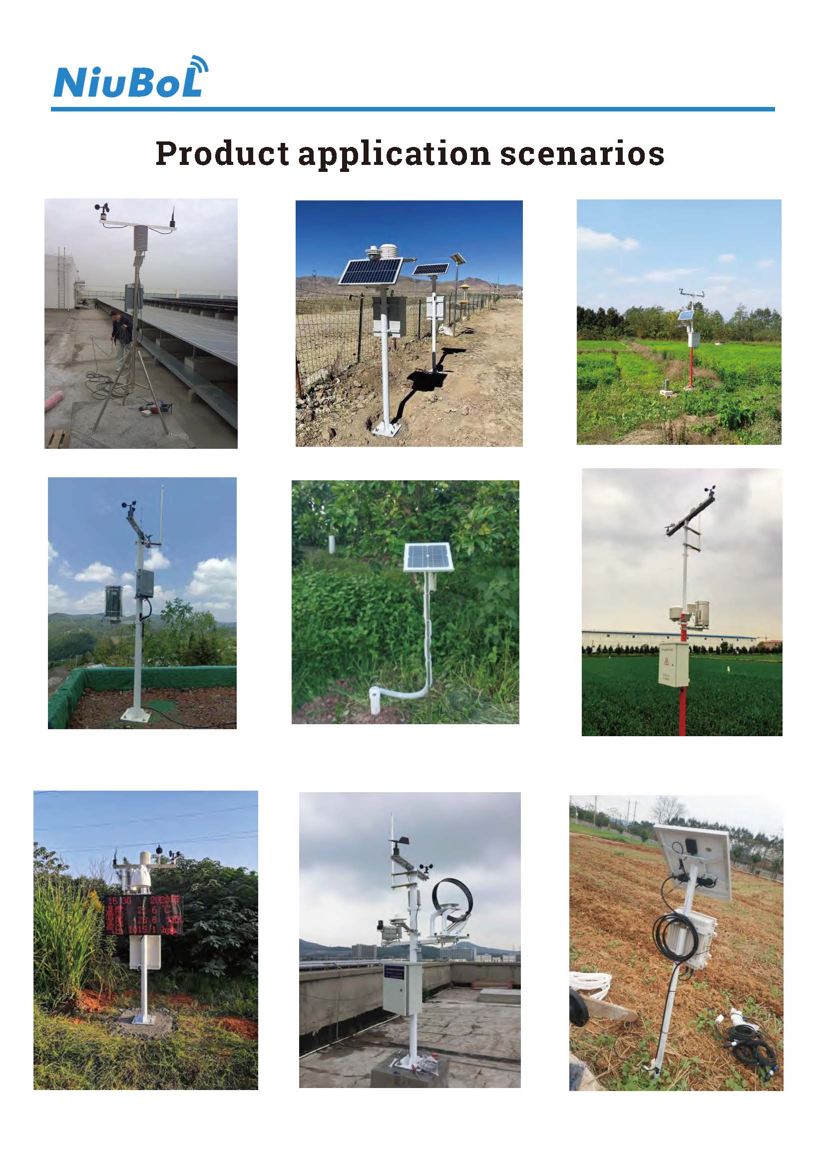
Assembly reference: Automatic Weather Station Installation Training Manual (PDF). Use the station drawing together with the procedure for each installed instrument.
 Automatic-Weather-Station(aws)Installation-Training-Manual.pdf
Small meteorological station installation can fail even when power and communications appear normal. Remove identified transport restraints, retain operational protection and establish the correct sensor orientation. These checks help the installer reach valid observations without unnecessary calibration changes or damage to the measuring parts.
Prev:Rain Gauge Weather Station: When Extra Measurements Add Useful Context
Next:Commercial Weather Station Height: 2.5 m, 3.5 m or 10 m?
Related recommendations
Sensors & Weather Stations Catalog
 Agriculture Sensors and Weather Stations Catalog-NiuBoL.pdf
Weather Stations Catalog-NiuBoL.pdf
Agriculture Sensors Catalog-NiuBoL.pdf
Water Quality Sensor Catalog-NiuBoL.pdf
Related products
 Combined air temperature and relative humidity sensor
 TDR Soil Moisture & Temperature Sensor for irrigation| RS485 |4-20mA| NBL-S-THR
 Soil pH sensor RS485 soil Testing instrument soil ph meter for agriculture |NBL-S-PH
 Wind Speed sensor Output Modbus/RS485/Analog/0-5V/4-20mA
 Tipping bucket rain gauge for weather monitoring auto rainfall sensor RS485/Outdoor/stainless steel
 Pyranometer Solar Radiation Sensor 4-20mA/RS485


Screenshot, WhatsApp to identify the QR code
WhatsApp number:+8615367865107
(Click on WhatsApp to copy and add friends)

