

— Blogs —
—Products—
 Consumer hotline +8618073152920
WhatsApp:+8615367865107
Address:Room 102, District D, Houhu Industrial Park, Yuelu District, Changsha City, Hunan Province, China
Product knowledge
Time:2022-11-20 19:43:08 Popularity:2189
Quick Answer: An agricultural IoT monitoring system connects field sensors to a logger or gateway, then moves validated data to a platform. Remote control is a separate function that needs rules, actuators, interlocks and a fail-safe state. During agricultural IoT commissioning, follow a real observation through each stage and test what happens when its connection or supply is interrupted.
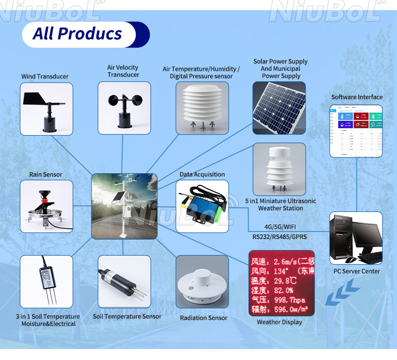
| Layer | Function | Procurement check |
|---|---|---|
| Field measurement | Weather, soil, water or crop sensors | Parameter, range, accuracy, placement and maintenance |
| Local acquisition | Logger, PLC or RTU reads and timestamps data | Channel count, RS485 settings, register map and local storage |
| Remote communication | Gateway sends records through the available network | Coverage, SIM or network costs, protocol and outage recovery |
| Application | Dashboard, alarms, reports and optional API | Data ownership, access roles, retention and export |
Select one real point and identify its physical location, sensor, acquisition input and application tag. Compare the instrument value, logger value, transmitted message and customer display at the same time. Agree which stage timestamps the measurement and which stage records receipt.
For an illustrative scaling test, an integer value of 321 with a declared factor of 0.1 represents 32.1 in the declared unit. It does not establish a soil moisture percentage until the channel definition and unit are confirmed. The example is not a NiuBoL register assignment; use the register map for the delivered instrument.
Change the input using a suitable reference or approved simulation and verify every stage. If the logger changes but the dashboard does not, investigate the mapping and transmission rather than immediately replacing the field sensor. If two dashboard tags change together unexpectedly, check for reused addresses or tag definitions.
An RS485 Modbus RTU sensor normally communicates with a nearby logger or gateway. The sensor does not acquire 4G, Wi-Fi or cloud capability merely because it has RS485. Confirm addresses, baud rate, parity, register definitions, units and scaling for the field bus, then specify the gateway's server protocol separately.
Do not connect a second active Modbus master to an existing field bus merely to add a remote view. Use the intended gateway architecture or a separate supported interface. Retain existing controller operation while the monitoring connection is assessed.
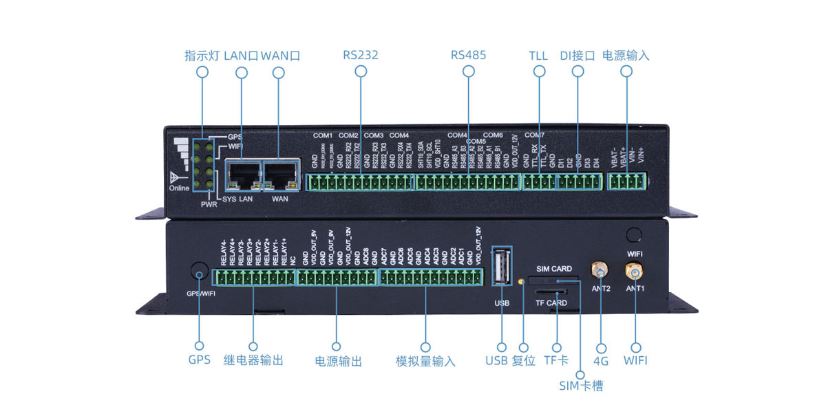
A NiuBoL TG462 / TG462S data logger option provides serial and analog acquisition. The following characteristics help define the equipment schedule, but software mapping and the actual configuration still require testing.
| Acquisition characteristic | TG462 / TG462S option | Commissioning check |
|---|---|---|
| Serial connections | 3 RS485 interfaces and 4 RS232 interfaces, including a debug interface. | Confirm port availability, any shared functions and permitted device polling. |
| Analog acquisition | 8 channels, 12-bit ADC; 4-20 mA input, or optional 0-5 V arrangement. | Check the purchased input type, wiring and engineering scale. |
| Data protocols | Modbus RTU/TCP and MQTT functions. | Test register mapping, server messages and authentication separately. |
| Supply | 5-35 V DC input. | Check sensor supply requirements separately from gateway input voltage. |
| Operating environment | -35 to +75 degrees C; IP30 housing. | Provide a suitable field enclosure and manage internal heat and condensation. |
| Network and cable | Ethernet and the selected cellular variant; specified serial/analog field wiring. | Match destination bands, cable construction, routing and protected entries. |
The gateway's analog resolution does not give the complete measurement accuracy. A sensor, wiring and input circuit contribute their own errors. An input simulation can verify acquisition scaling, but it does not calibrate the soil or weather measurement.
Check voltage at the installed instrument under the intended operating condition. The gateway can accept 5-35 V DC, while an NBL-S-THR soil sensor requires 12-24 V DC. A common supply within the gateway's permitted range can still be outside the probe's range. Do not assign the gateway input limits to every peripheral power output or connected instrument.
Include startup and radio activity in the check if the supply is shared. A remote application may remain accessible while a sensor repeatedly restarts or stops replying. Inspect supply and field-bus behavior together before attributing intermittent values to server software. Retain the event timing so the different symptoms can be compared.
For an analog channel, establish what electrical signal represents a legitimate process zero. In an ordered 4-20 mA arrangement, the configured lower measurement value normally corresponds to 4 mA; a missing-current condition needs the input's defined treatment rather than an automatic valid zero. Do not impose a particular fault-current code unless the actual devices implement it.
Use qualified personnel and suitable isolated test arrangements for electrical checks. A temporary input simulation should not inadvertently energize an actuator or disable a protective function. Distinguish the test configuration from normal operation and restore the intended wiring and settings before accepting the point.
Local memory capacity and outage recovery are different functions. A useful recovery test needs the expected record interval, a controlled network interruption and inspection of the restored records. Verify the purchased implementation rather than assuming a memory card guarantees replay.
For a defined test, six observations taken at ten-minute intervals from 12:00 through 12:50 should remain six distinct observations after replay. Their arrival time may be later than their measurement time. The example describes test bookkeeping, not a default logger interval or storage guarantee.
Check gaps, duplicate messages and order of arrival in the receiving system. A chart can appear continuous because it joins points across an outage. Inspect the actual records and validity indications. Do not accept a smooth line as proof that the missing period was measured.
Test a power restart separately from a network interruption. Confirm clock recovery, preserved settings and any effect on pulse counters or accumulated values. The system should distinguish an instrument reset from a legitimate process change so a restart does not become a false irrigation event.
An alarm has a measurement condition, timing rule and operational recipient. Test whether a short disturbance is filtered as intended and whether sustained conditions reach the correct person. A phone receiving a message establishes only part of the workflow.
Review stale-data alarms separately from high or low process alarms. A disconnected soil probe should not report a credible zero, while an old acceptable value should not keep automatic operation enabled indefinitely. Agree on the indication and response for each unavailable input.
Set permissions so field staff can perform necessary checks without changing unrelated device or farm settings. Verify export access and retention for the required project records. These functions should be demonstrated with the intended account role, not only the administrator's account.
Soil moisture and weather data may support irrigation decisions, but automatic valve control requires a controller, actuator, hydraulic checks, threshold logic, manual override and a defined response to missing or implausible data. The platform should distinguish a zero reading from a communication failure.
For an irrigation control test, follow a permitted command through controller output and valve status to suitable hydraulic feedback. A relay output changing does not prove that a valve opened or that water reached the intended block. Keep pump protection and other time-critical safeguards in a suitable local arrangement.
A relay rating is not a universal approval to switch a pump motor directly. Match the control circuit, contactors and protection through the electrical design. Test manual override and the response to loss of a critical input before allowing automatic operation.
Also define who owns the data, who can change device settings, how long records are retained and how configuration changes are logged. These items matter when several contractors share the sensor, communication and software scope.
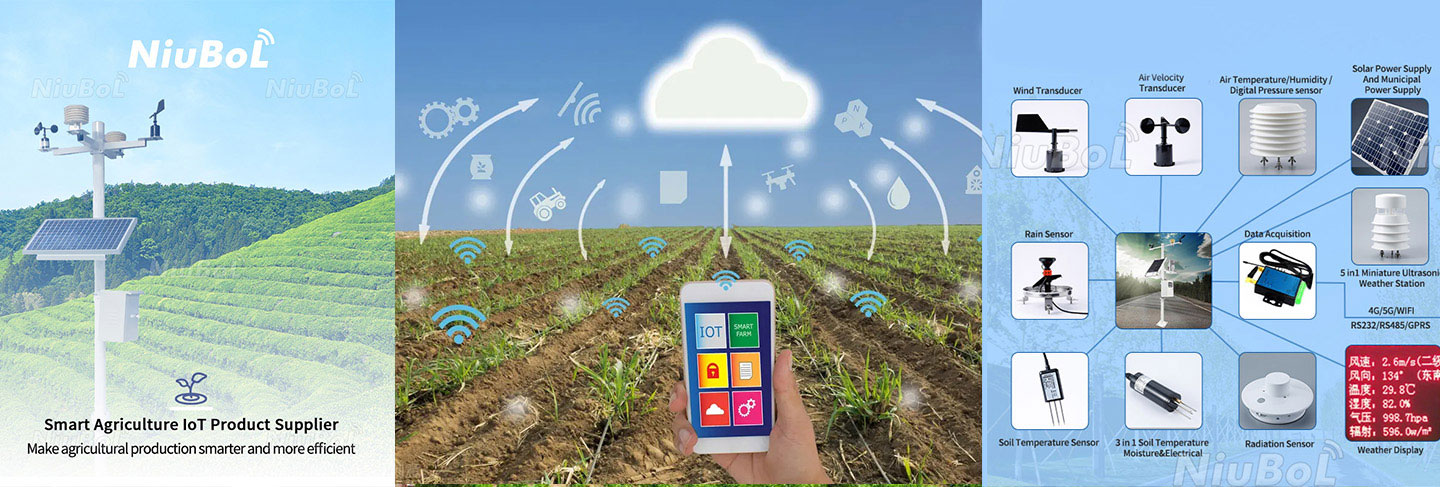
Related equipment can be selected from NiuBoL agricultural sensors and IoT communication devices.
Keep the observations from those tests with the final point and tag definitions. After a sensor replacement, confirm the new device address, scale and location assignment. A replacement that responds on the bus can still send data to the wrong field name.
For procurement, separate the instruments, field wiring, acquisition hardware, network service and application configuration. Ask NiuBoL to assess the measurement and interface list. Identify which party supplies control logic and performs the site tests so responsibility does not stop at a successful hardware demonstration.
No. Confirm the radio protocol, gateway compatibility, frequency plan and local regulatory requirements.
The practical number depends on power, addressing, cable, topology, baud rate and gateway limits. Approve the bus design rather than relying on a theoretical maximum.
No. Check register interpretation, scaling, unit and physical point assignment. Compare the observation through the logger, transmitted message and display using a suitable input change.
No. Test storage, replay, original timestamps and duplicate handling in the actual implementation. Capacity does not establish that the receiving application gets a complete usable record.
Acquisition testing checks wiring, scaling and data handling. Sensor calibration assesses the measurement against an appropriate reference. A simulated electrical input does not establish the accuracy of the installed environmental observation.
Not for functions requiring timely local protection. Select local control and interlocks for the duty, and test their operation when the server or network is unavailable.
List parameters, sites, quantities, interfaces, cable lengths, power, network conditions, platform or API scope, control functions and acceptance tests.
Agricultural IoT is a data and control architecture, not a collection of connected sensors. Clear interfaces and acceptance tests make the system maintainable.
Prev:Agricultural IOT monitoring system
Next:Modern agricultural IOT remote monitoring system overall design
Related recommendations
Sensors & Weather Stations Catalog
 Agriculture Sensors and Weather Stations Catalog-NiuBoL.pdf
Weather Stations Catalog-NiuBoL.pdf
Agriculture Sensors Catalog-NiuBoL.pdf
Water Quality Sensor Catalog-NiuBoL.pdf
Related products
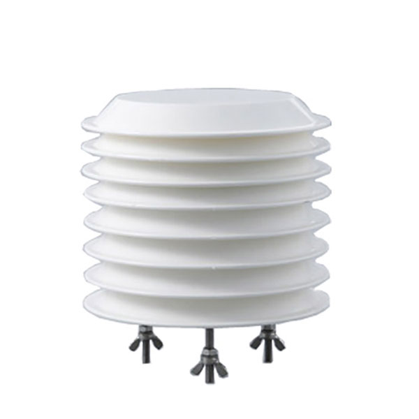 Combined air temperature and relative humidity sensor
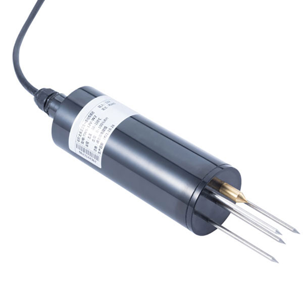 TDR Soil Moisture & Temperature Sensor for irrigation| RS485 |4-20mA| NBL-S-THR
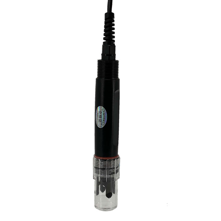 Soil pH sensor RS485 soil Testing instrument soil ph meter for agriculture |NBL-S-PH
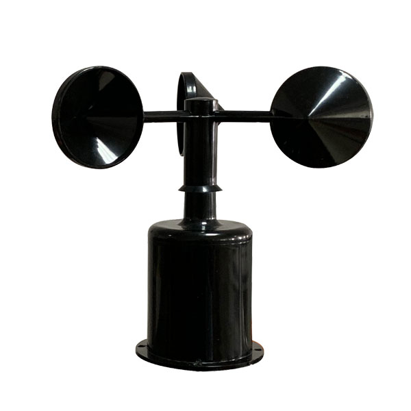 Wind Speed sensor Output Modbus/RS485/Analog/0-5V/4-20mA
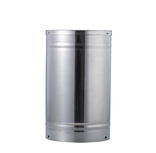 Tipping bucket rain gauge for weather monitoring auto rainfall sensor RS485/Outdoor/stainless steel
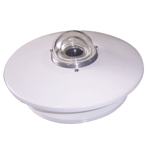 Pyranometer Solar Radiation Sensor 4-20mA/RS485


Screenshot, WhatsApp to identify the QR code
WhatsApp number:+8615367865107
(Click on WhatsApp to copy and add friends)