





— Blogs —
—Products—
 Consumer hotline +8618073152920
WhatsApp:+8615367865107
Address:Room 102, District D, Houhu Industrial Park, Yuelu District, Changsha City, Hunan Province, China
Product knowledge
Time:2024-05-18 10:45:37 Popularity:1845
Quick Answer: Multi-depth soil moisture sensor applications are most useful when the decision depends on how water changes with depth. A profile can show a wet surface above a drying root zone, the progress of an irrigation wetting front or persistent wetness in a lower layer. It does not directly measure nutrient concentration, pollutants, root uptake or drainage volume. Choose depths and monitoring positions around the crop, soil and irrigation layout before selecting a tube length.
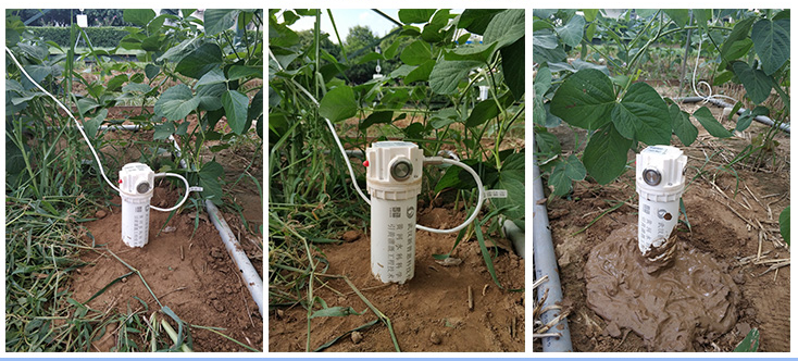
A single soil moisture value cannot explain every irrigation problem. After a short application, the upper layer may respond while deeper roots remain in drier soil. Later, the surface may dry through evaporation while moisture remains available below. Root-zone soil moisture monitoring separates these situations by preserving the individual depth channels instead of reducing them immediately to one average.
The NiuBoL tube-type sensor uses dielectric measurement to estimate volumetric water content and measures soil temperature at its sensing levels. The NBL-S-TMM configuration has standard depths of 10, 20, 30 and 40 cm, with other layer arrangements available to order. The actual sensing depths are more important to the application than the overall body length. Do not assume the entire length is a continuous moisture measurement.
Volumetric water content describes the volume of water relative to the bulk soil volume. It is not automatically the proportion of plant-available water remaining. Interpreting a reading requires local soil characteristics and an appropriate management baseline. A sandy layer and a clay layer can have different useful moisture conditions even when their displayed percentages are equal.
For orchard irrigation monitoring, position the profile in relation to the drip line, emitter spacing and active root distribution. A sensor immediately below an emitter describes a different part of the wetting pattern from a sensor between emitters. Record that position. A second point may be needed where soil type, slope or the irrigation layout changes; extra depth channels do not substitute for horizontal coverage.
Compare layer trends before irrigation, during water application and during redistribution. If only the upper channel responds repeatedly, investigate whether the application duration, delivery rate or sensor position explains the pattern. If a lower channel changes, it indicates wetting at that observation depth, not a measured drainage volume or proof of fertilizer loss. Use flow records and additional sampling when those are the decisions being made.
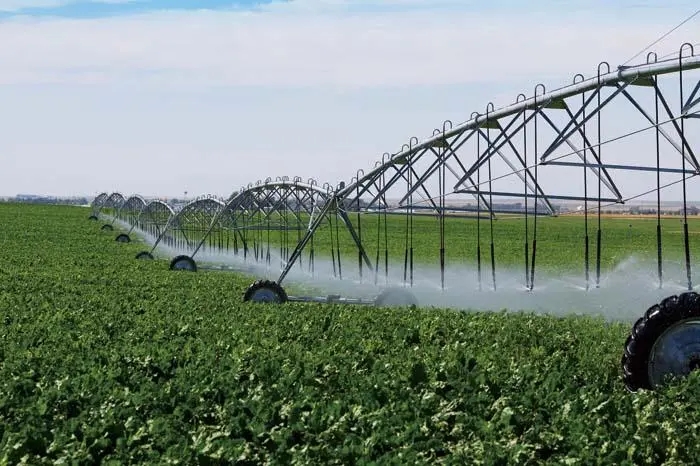
Center-pivot and other field systems need representative locations within the management zone. Avoid treating a wheel rut, a leaking fitting or an isolated low spot as the field average unless that specific problem is the monitoring objective. Combine the soil profile with applied-water and rainfall records so an unexplained moisture increase is investigated before the irrigation schedule is changed.
Soil-grown greenhouse crops can use profile monitoring to distinguish surface wetting from moisture deeper in the bed. Temperature channels help describe conditions around those layers. An irrigation controller can use selected readings, but the moisture thresholds must match the soil, crop stage and management objective. Do not copy one setpoint between different beds simply because the sensors share a model number.
Small pots, shallow trays, rockwool slabs and narrow substrate bags may not provide the geometry or material response needed by a field tube sensor. A substrate-specific or shorter point sensor may be more appropriate. Confirm that the active sensing zones are fully surrounded by the intended medium and not partly exposed to air, a container wall or a neighboring irrigation channel.
Fertigation adds another reason to distinguish channels. A water-content profile is not an NPK measurement, and it does not quantify fertilizer concentration. Use an appropriate EC or nutrient method if salinity or dosing is the management task. Check dielectric measurement performance in the actual medium and expected conductivity conditions rather than assuming complete immunity to salts.
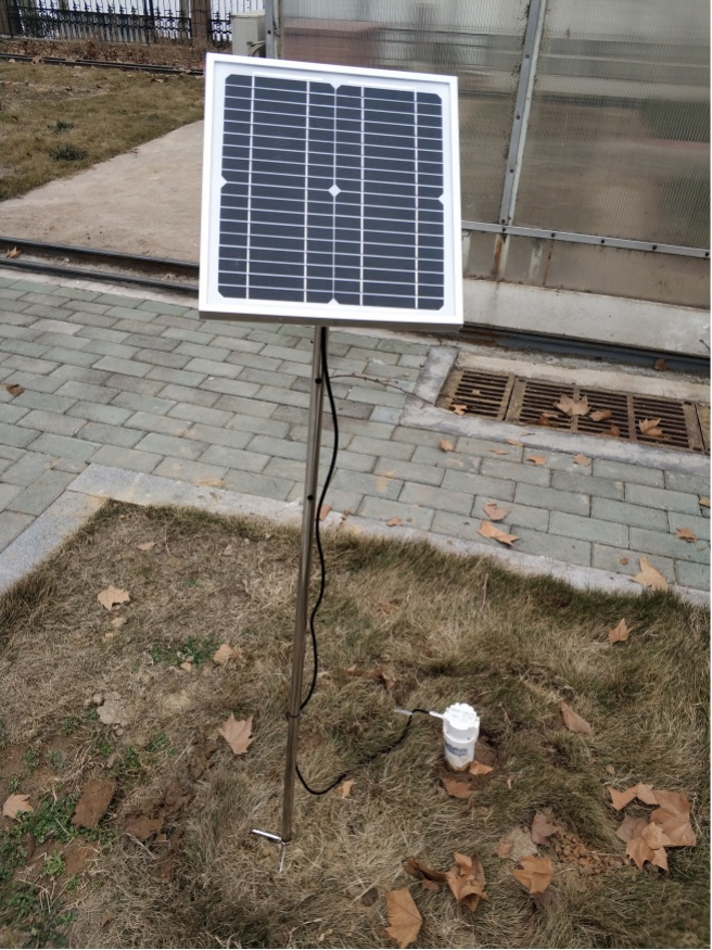
Young trees and established stands can draw on different depths. Select the profile around the relevant rooting zone and local soil horizons. Compare drying patterns with rainfall and seasonal observations to identify periods that warrant field inspection. Soil moisture alone is not a forest-fire warning system and cannot diagnose a pest outbreak; those require their own observations and response procedures.
Pasture soil monitoring often needs to distinguish a brief surface rain response from moisture sustained below. Protect the installation against livestock, mowing and vehicle damage without creating a water-collecting depression around it. Keep grazed and ungrazed plots, or contrasting soil zones, as separate sites. One tube cannot establish pasture productivity or determine stocking rates without the wider agronomic assessment.
For soil moisture research, preserve depth, time and site metadata alongside each value. Rainfall, soil texture, temperature and groundwater information can help interpret changes, but a profile is not a piezometer or direct seepage-flow meter. A wet lower layer may reflect several processes. Select water-level instruments, drainage measurements or chemical sampling when the study needs to distinguish them.
Repeated observations at a fixed point are useful for comparing events. Moving the tube between plots produces a different type of dataset because the installation and contact conditions change. Mark a relocation as a new location or installation period; do not join it invisibly into a long-term soil profile monitoring record.

The following parameters describe the NBL-S-TMM tube configuration, not every soil sensor offered by NiuBoL. Different versions may use different power arrangements or options. Specify the delivered model and depth schedule together so the quotation, channel map and installation drawing describe the same equipment.
| Parameter | NBL-S-TMM configuration | Application consequence |
|---|---|---|
| Measured quantities | Soil volumetric water content and soil temperature at discrete depths | No direct nutrient or pollutant concentration measurement |
| Standard depth arrangement | 10, 20, 30 and 40 cm; custom arrangements up to ten layers | Choose the required layers before ordering |
| Water-content measurement range | Dry to moisture-saturated soil | Interpret against local soil conditions, not a universal irrigation percentage |
| Water-content accuracy and resolution | +/-3% under laboratory conditions; 0.1% resolution | The laboratory figure is not a field-wide accuracy guarantee |
| Temperature | -40 to +80 degrees C; accuracy +/-0.5 degrees C; resolution 0.1 degrees C | Retain temperature by depth rather than assigning one value to the entire profile |
| Electrical supply and consumption | DC 12 V or suitable solar power arrangement; sleep current below 1 mA, sampling current below 70 mA | Include logger and communications consumption in station sizing |
| Communication | RS485 Modbus; Modbus RTU integration requires the delivered register map and serial settings | Map each layer explicitly in the receiving system |
| Dimensions | 63 mm diameter; standard length about 1000 mm, dependent on node configuration | Check tooling, hole depth and sensing positions before installation |
| Protection and environment | Above-ground part IP67; underground part IP68; -40 to +80 degrees C operating environment | Protect connectors and exposed equipment separately |
| Construction and cabling | Plastic tube with epoxy sealing; cable specification selected with the installation | Confirm exposed cable UV suitability, jacket material and mechanical protection |
For electrical planning, 70 mA at 12 V corresponds to 0.84 W. Because the specified sampling current is below 70 mA, that is a reference ceiling for the sensor's sampling load, not an average station demand. Radio operation, sampling duration, sleep behavior and the collector determine the actual energy budget. Do not promise battery autonomy from this multiplication.
Prepare a bore suited to the tube and the soil, keeping the sensor's zero-depth mark aligned with the intended ground reference. Follow the installation procedure for the selected tube, including the specified soil slurry where required to establish contact. Do not hammer a tube through stones or use a loose oversized hole and assume the resulting gap is harmless.
The installation itself disturbs the soil. Record when it was completed and allow for local redistribution before treating early readings as a normal baseline. Inspect whether surface water is flowing down the installation annulus rather than through the surrounding profile. An immediate deep response to every small irrigation pulse warrants a contact and installation check, not an automatic conclusion that water has passed through the whole root zone.
During a suitable observed event, compare the channel sequence with rainfall or irrigation timing and inspect the field. A profile need not always wet from the shallowest sensor downward: preferential flow, layered soils and lateral movement can complicate the pattern. Investigate a surprising response using the site conditions instead of forcing the readings into an expected curve.
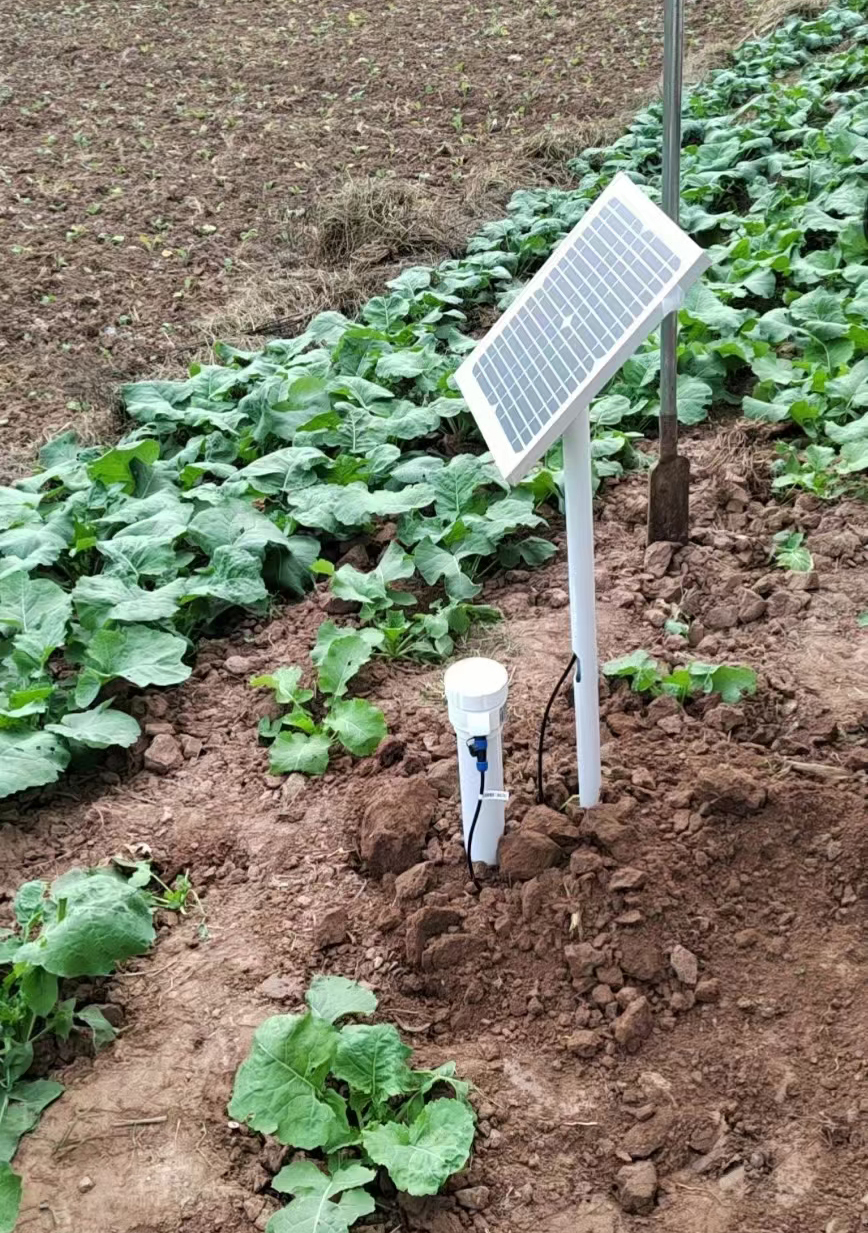
For RS485 Modbus RTU acquisition, identify the value format, scale and depth associated with every register. The NBL-S-TMM wiring uses red for positive power, black for power ground, yellow for RS485 positive and blue for RS485 negative. Verify the delivered connector and wiring before energizing; the color convention should not be assumed for another sensor family.
A data logger or RTU can store the profile and transfer it to a remote platform. Cellular access requires the appropriate communications hardware and service. For a research station, acquisition intervals should resolve the events of interest. For irrigation control, also define what happens when a layer is unavailable, implausible or under maintenance. A missing value must not become an instruction to keep watering.
Use crop- and soil-specific thresholds and appropriate control limits. A deep channel can help review application duration, but automatic shutoff should be tested against field response and hydraulic delay. Valve commands are not measured flow. Where confirmation of water application matters, include flow or pressure feedback rather than interpreting a controller output as proof of delivered water.
Send NiuBoL the crop, soil horizons, proposed depths, irrigation pattern and existing collector requirements when requesting a configuration. Identify whether the project needs fixed observations or portable spot checks. Ask for the depth-to-register schedule and installation accessories with the quote; a longer tube is not necessarily the right substitute for a differently spaced sensing arrangement.

Choose a profile when vertical differences change the decision, such as whether water has reached deeper roots. Use single-point sensors when only one depth matters or when independent placement across a shallow bed is more useful than several levels at one location.
No. Plant-available water depends on local soil properties and the management reference values used. Establish those relationships before calculating depletion or assigning irrigation triggers. Equal volumetric percentages in different soils need not represent equal crop stress.
No. It indicates a water-content change at the sensing depth. Drainage volume needs an appropriate water-balance or direct measurement approach, and nitrogen loss also needs concentration information. Keep these as separate measurements or explicitly defined estimates.
Only if the monitored zone is sufficiently uniform for the intended decision. Different soil types, slopes, emitters and crop conditions can require separate points. Additional layers improve vertical information, not the horizontal coverage of the orchard.
Not automatically. Soil texture, contact, bulk density and conductivity can affect field response. Check performance with an appropriate local reference and evaluate whether the installed system can distinguish the changes needed for irrigation or research.
Not without verifying the sensing geometry and material response. A field tube may be too long or have sensing zones affected by air and container boundaries. A shorter or substrate-specific instrument may answer that task more reliably.
List the depth configuration, output, power arrangement, cable and protection, installation tooling, logger interface and any remote communications. Separate sensor supply from platform access and field installation so competing offers describe comparable work.
Inspect exposed cables, solar equipment and the ground surface without repeatedly disturbing the tube. Record any removal, soil work or relocation. After such changes, recheck depth references and field response before treating the observations as continuous with the earlier installation.
Multi-depth soil moisture sensor applications should be selected around a specific vertical-water question. Preserve each layer's meaning, place the tube in a representative irrigation or research zone and check contact after installation. The resulting profile can guide field decisions, while nutrient analysis, water-level measurements and delivered-water feedback remain separate tasks.
 NBL-S-TMM-Tubular-Multi-Layer-Soil-Moisture-Sensor-Meter.pdf
Related recommendations
Sensors & Weather Stations Catalog
 Agriculture Sensors and Weather Stations Catalog-NiuBoL.pdf
Weather Stations Catalog-NiuBoL.pdf
Agriculture Sensors Catalog-NiuBoL.pdf
Water Quality Sensor Catalog-NiuBoL.pdf
Related products
 Combined air temperature and relative humidity sensor
 TDR Soil Moisture & Temperature Sensor for irrigation| RS485 |4-20mA| NBL-S-THR
 Soil pH sensor RS485 soil Testing instrument soil ph meter for agriculture |NBL-S-PH
 Wind Speed sensor Output Modbus/RS485/Analog/0-5V/4-20mA
 Tipping bucket rain gauge for weather monitoring auto rainfall sensor RS485/Outdoor/stainless steel
 Pyranometer Solar Radiation Sensor 4-20mA/RS485


Screenshot, WhatsApp to identify the QR code
WhatsApp number:+8615367865107
(Click on WhatsApp to copy and add friends)

