

— Blogs —
—Products—
 Consumer hotline +8618073152920
WhatsApp:+8615367865107
Address:Room 102, District D, Houhu Industrial Park, Yuelu District, Changsha City, Hunan Province, China
Product knowledge
Time:2021-12-21 21:49:03 Popularity:2563
Quick answer: Standard copper Ethernet channels are normally designed around a 100 m channel, including patch cords. PoE must satisfy both data-link and power requirements within that channel. Claims of longer reach may use nonstandard extension modes, reduced data rates, repeaters or fiber plus local power and must be evaluated as a different design.
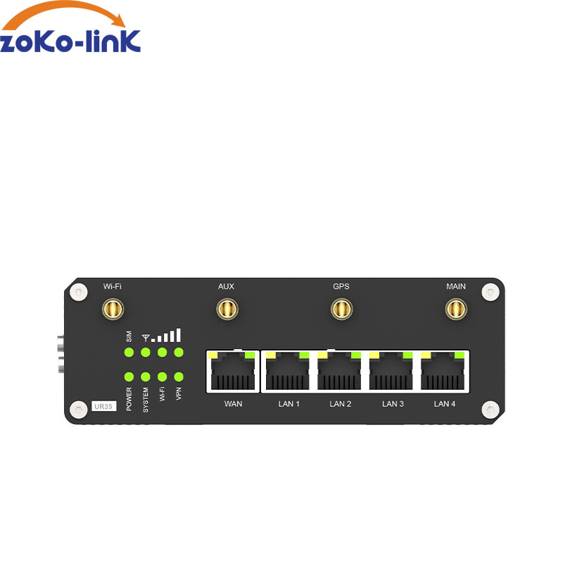
The familiar 100 m design applies to a standard copper Ethernet channel, not to a reel length plus unlimited patching. Count the installed cable, patch cords and connecting arrangement. The cable category must suit the Ethernet rate and power application. Using a higher category does not automatically authorize a longer standard channel.
Power sourcing equipment, or PSE, supplies energy; the powered device, or PD, receives it. A compliant connection detects and classifies the PD before delivering the applicable operating power. An RJ45 socket, antenna connector or industrial enclosure does not identify a device as either a PoE source or load. Confirm the actual model's port functions.
These PoE distance limits concern conventional multi-pair Ethernet designs. Long-reach Ethernet products, single-pair systems and vendor extension modes may use different physical interfaces or operating conditions. Assess the specified technology as its own design rather than applying the 100 m figure to every product carrying an Ethernet label.
A port's source rating is not the same as power available at the remote equipment. Some power is lost in the channel. Also distinguish a Type from the particular supported Class: equipment need not provide the highest power associated with its Type. The selected source and load must negotiate an allocation that supports the required device operation.
| Common PoE type | Upper PSE power level | Corresponding PD level | Selection consequence |
|---|---|---|---|
| Type 1, IEEE 802.3af | 15.4 W | Approximately 13 W | Do not assign the whole PSE rating to the remote load |
| Type 2, IEEE 802.3at | 30 W | 25.5 W | Confirm the allocated Class and actual peak operating mode |
| Type 3, IEEE 802.3bt | 60 W | 51 W | The higher power classes require the appropriate four-pair arrangement |
| Type 4, IEEE 802.3bt | 90 W | 71.3 W | Check the supported Class, cabling and thermal conditions |
These are standards-based power levels, not specifications for the communications devices pictured here. Keep PSE capabilities and PD power allocations separate in the equipment schedule, and confirm the Classes supported by the selected source and endpoint.
Add the maximum input power of every powered device, then compare the total with the switch budget at the expected cabinet temperature. Keep spare capacity for startup, cold-weather heaters and later additions. If a port powers a camera with infrared illumination, test it at night or force the high-load mode during commissioning.
Check the power source feeding the switch as well. A DC supply can be correctly sized for the switch electronics but still be too small for all PoE loads.
Consider an illustrative eight-port design with six ports allocated 15.4 W each and two ports allocated 30 W each. The PSE allocation is 6 x 15.4 + 2 x 30 = 152.4 W. A switch with a 120 W PoE budget would be short by 32.4 W, even though every individual port could support its assigned Class. This is a budgeting example, not a NiuBoL switch specification.
Use a consistent source-side basis for this check; do not mix some PD input powers with other PSE allocations. If supported power negotiation or measured-load management changes the reservation, evaluate that behavior with the chosen devices. A design that works because some loads happen to be idle may fail after a simultaneous restart.
Cabinet temperature and input-supply conditions can reduce the available budget. Check the applicable operating curve and power priority behavior. Redundant DC inputs do not mean their ratings can always be added, and battery backup for switch electronics alone does not establish backup power for all downstream devices.
A powered device needs enough voltage and power after cable loss, while Ethernet must also maintain signal integrity. Conductor material, gauge, connector quality, temperature and bundled cables affect resistance and heat. A cable that powers a device is not necessarily carrying error-free data.
| Check | Project requirement |
|---|---|
| PoE standard and class | Match the switch output and powered-device requirement. |
| Power budget | Calculate total switch load and per-port demand, including startup and heating accessories. |
| Cable channel | Use compliant copper cable, connectors and documented channel length. |
| Environment | Account for cabinet temperature, outdoor surge exposure, moisture and grounding. |
| Network load | Confirm required link speed and traffic, especially for cameras. |
Check the complete Ethernet cable channel for data performance and DC conditions. A basic continuity tester may find an open conductor without establishing channel bandwidth, insertion loss or resistance balance. A link can also operate at a lower negotiated rate than the application expects. Record the required rate and test the installed channel for that task.
Resistance creates a voltage drop and heating. In a deliberately simplified example, an effective powered-path resistance of 4 ohms carrying 0.5 A gives a 2 V drop and 1 W loss using V = IR and P = I squared R. Those assumed values are not a cable-standard limit or a full PoE pairset model. They show why a light-load test can miss a problem that appears at higher current.
Specify suitable compliant copper cable and check conductor construction, connectors and installation conditions. A cable jacket category label alone does not establish the resistance of an entire installed route. Outdoor moisture, poor terminations and damaged pairs can introduce faults that changing the PoE Class will not repair.
For distances beyond the standard copper channel, use a designed solution: an intermediate PoE extender, a powered network cabinet, or fiber with power available at the remote end. Each option changes maintenance, surge exposure and failure points. “Extend mode” on a switch may reduce link speed and does not remove cable-quality limits.
| Long-link option | Useful when | Additional check |
|---|---|---|
| PoE extender or repeater | A suitable intermediate device can regenerate the data link | Account for its own consumption, output power, permitted segments and accessibility |
| Intermediate powered cabinet | Local power and a maintainable location are available | Treat each copper segment separately and assess backup power and environment |
| Fiber backhaul | The route is long or optical data isolation is needed | Choose transceivers and fiber for the route; provide far-end power |
| Cellular backhaul | A remote station has suitable coverage and local power | Verify coverage, service and acquisition needs; it does not carry PoE energy to the site |
PoE extender selection must include the complete chain. A PoE-powered repeater consumes some of the upstream power and cannot promise the original port's entire rating at its output. Do not assume every extender can be cascaded indefinitely. Check the manufacturer's supported arrangement, data rate and available downstream power under the proposed route conditions.
A fiber link carries data, not electrical power to the camera or field gateway. Plan the supply at the remote end, including any local PSE needed there. Optical transmission can remove the conductive data path between sites; metallic armor, local power systems and other conductors still need their own bonding and protection assessment.
A monitoring cabinet may contain both Ethernet equipment and serial instruments. A NiuBoL RS485 sensor gateway can acquire or transfer the selected serial measurements into the project architecture, while a switch handles Ethernet forwarding. Modbus RTU uses serial framing; an ordinary Ethernet switch does not convert the sensor registers into Modbus TCP or a platform message by itself.
The NiuBoL TG462 data-collection gateway is an example of separate acquisition equipment. Verify its delivered power input, serial mapping and network interface. Do not apply PoE voltage directly to a sensor's DC supply or assume an Ethernet-equipped gateway is a PoE PD. Where a suitable splitter is selected, its output voltage, polarity and available load power must match the downstream equipment.
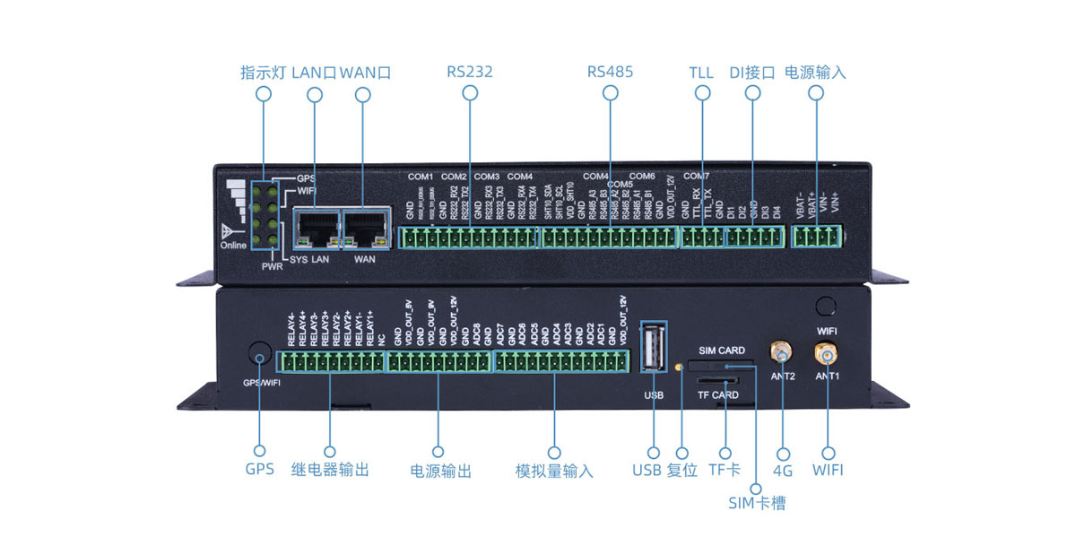
Check DIN-rail mounting, DC input range, redundant power needs, operating temperature and surge protection. Outdoor copper links between structures require a grounding and lightning-protection review. Fiber provides electrical isolation between buildings but still requires local power for the end device.
Measure the cable, verify negotiated link speed, load every required port and test the far-end device during peak consumption. Review packet errors and voltage under load, then document spare power budget.
For a camera, trigger the appropriate infrared, heater or movement mode during the test. For a remote monitoring cabinet, start the actual instruments and communications devices together. Observe the source allocation, far-end operation and packet errors while all required ports are loaded. A daylight ping from one lightly loaded endpoint is not an acceptance test for the full installation.
If a link fails intermittently, separate power failure from data failure. Check whether the PSE reports denial, overload or repeated detection; check whether the Ethernet port renegotiates or records errors. Then compare the same endpoint on a known-good short channel. This sequence helps avoid replacing a sensor gateway when the actual fault is an overloaded source or damaged cable.
Where copper is impractical, a separately powered 4G router can provide an alternative data path, subject to site coverage. It does not extend the PoE cable or remove the need for local energy. For a NiuBoL integration inquiry, describe the sensor interfaces, equipment input powers, route length and existing network so the acquisition and backhaul roles can be selected separately.
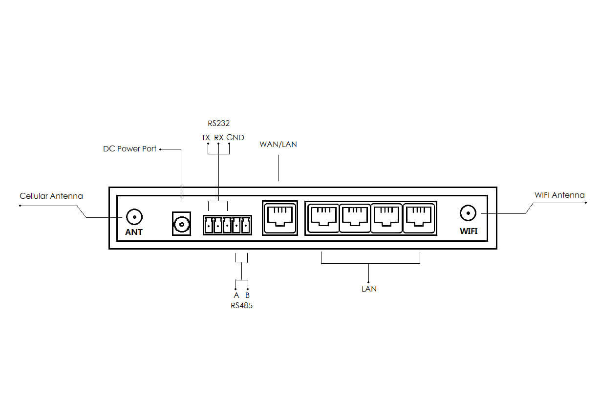
No. Better cable does not change the standard channel design into an unlimited link. Count patching and connectors as part of the installed channel, and assess any long-reach product using its specified data rate and power conditions.
Only if the total PoE budget, per-port capability, input supply and operating temperature support that allocation. Port count and individual port ratings do not establish the simultaneous total.
Do not assume so. Type 2's corresponding PD level is 25.5 W. Identify the device's actual requirement and select a compatible allocation with allowance for the channel and any conversion equipment.
No. A PoE-powered extender uses energy and introduces another output constraint. Evaluate its consumption and downstream capability under the proposed topology rather than copying the upstream rating to the far endpoint.
No automatic compatibility should be assumed. Passive arrangements can use fixed voltage and pin assignments without the same detection and classification. Check both ends before connecting equipment; a matching RJ45 plug does not establish compatibility.
Not as a direct electrical or protocol connection. A suitable power-conversion arrangement and the required serial acquisition interface are separate requirements. Confirm the sensor's DC limits and polarity before making any connection.
Use it where route length, electrical separation or the operating environment favors an optical data link. Include compatible transceivers and a remote power plan; fiber does not deliver PoE power to the far device.
List endpoint power and Class, data rate, channel length, cable route, cabinet environment and backup requirements. Identify extenders, fiber hardware, remote supplies and serial gateways separately so the price describes a complete working arrangement.
PoE distance is a combined data, power and installation question. Design the channel from the required device load and verified cable path.
Resolve PoE distance limits by checking the data channel and remote power together. Beyond the standard copper arrangement, choose a supported repeater, cabinet, optical or wireless topology. Keep the sensor gateway's acquisition role separate from the network's power-delivery capability.
Related recommendations
Sensors & Weather Stations Catalog
 Agriculture Sensors and Weather Stations Catalog-NiuBoL.pdf
Weather Stations Catalog-NiuBoL.pdf
Agriculture Sensors Catalog-NiuBoL.pdf
Water Quality Sensor Catalog-NiuBoL.pdf
Related products
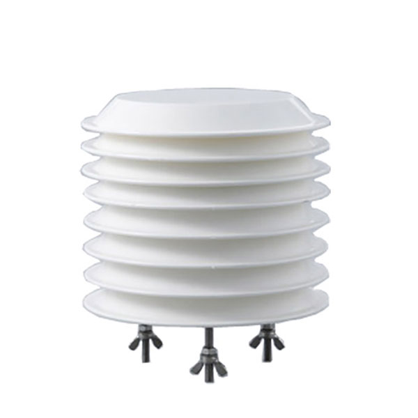 Combined air temperature and relative humidity sensor
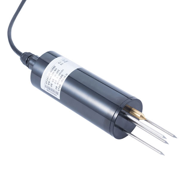 TDR Soil Moisture & Temperature Sensor for irrigation| RS485 |4-20mA| NBL-S-THR
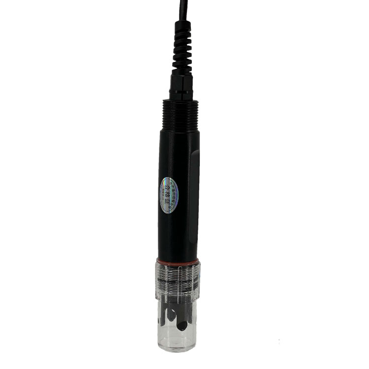 Soil pH sensor RS485 soil Testing instrument soil ph meter for agriculture |NBL-S-PH
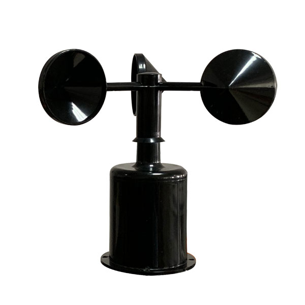 Wind Speed sensor Output Modbus/RS485/Analog/0-5V/4-20mA
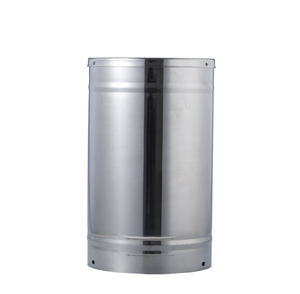 Tipping bucket rain gauge for weather monitoring auto rainfall sensor RS485/Outdoor/stainless steel
 Pyranometer Solar Radiation Sensor 4-20mA/RS485


Screenshot, WhatsApp to identify the QR code
WhatsApp number:+8615367865107
(Click on WhatsApp to copy and add friends)