

— Blogs —
—Products—
 Consumer hotline +8618073152920
 WhatsApp:+8615367865107
Address:Room 102, District D, Houhu Industrial Park, Yuelu District, Changsha City, Hunan Province, China
Product knowledge
Time:2021-12-30 21:44:30 Popularity:5209
RS485 and Modbus are not the same thing. RS485 defines the electrical communication interface used to transmit data, while Modbus defines the communication rules and data format used by devices to exchange information.
A simple way to understand the relationship is:
RS485 = How the electrical signal is transmitted
Modbus RTU = What the devices say to each other
This is why industrial sensors are commonly described as RS485 Modbus RTU sensors. RS485 provides the physical serial bus, while Modbus RTU defines addresses, commands, registers and data frames.
| Item | RS485 | Modbus RTU |
|---|---|---|
| Type | Electrical / physical communication standard | Communication protocol |
| Main Purpose | Transfers serial electrical signals | Defines how devices exchange data |
| Typical Wiring | Differential A/B pair | Uses the RS485 serial connection |
| Device Address | Not defined by RS485 itself | Each slave/server normally has a unique address |
| Registers | Not defined | Defines coils, inputs and data registers |
| Error Check | Not an application protocol function | CRC-16 in Modbus RTU frames |
RS485 is a serial communication electrical standard designed for reliable differential data transmission. Instead of transmitting a signal relative to ground on one wire, RS485 normally uses two signal conductors, commonly called A and B.
The receiver determines the data state from the voltage difference between the two conductors. This differential method provides better noise immunity than single-ended interfaces such as traditional RS232, making RS485 suitable for industrial sites and longer cable runs.
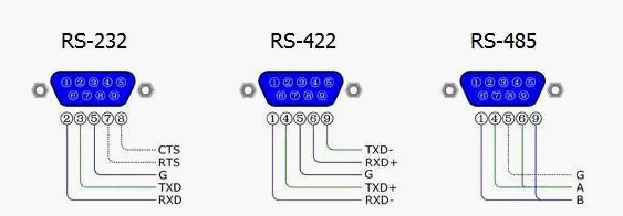
| Feature | RS232 | RS422 | RS485 |
|---|---|---|---|
| Signal Type | Single-ended | Differential | Differential |
| Typical Network | Point-to-point | One driver, multiple receivers | Multi-device bus |
| Noise Resistance | Lower | High | High |
| Common Industrial Use | Legacy serial equipment | Specialized serial systems | Sensors, PLCs, RTUs and field devices |
Modbus is an industrial communication protocol that defines how a controller and field devices exchange data.
A Modbus message can contain:
Device address
Function code
Register address
Number of registers
Data
Error-checking information
With Modbus RTU, these messages are transmitted through a serial interface such as RS485.
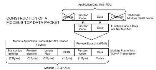
| Feature | Modbus RTU | Modbus TCP |
|---|---|---|
| Transport | Serial communication | Ethernet / TCP/IP |
| Common Physical Interface | RS485 | Ethernet |
| Error Checking | CRC | Handled by TCP/IP stack |
| Typical Application | Sensors and field buses | PLC, SCADA and Ethernet networks |
When an RS485 soil sensor is described as supporting Modbus RTU, the complete communication process is:
Sensor Measurement → Modbus Register → Modbus RTU Frame → RS485 A/B Electrical Signal → PLC / Data Logger
For example, a soil moisture sensor may store moisture at register 0x0000 and temperature at register 0x0001. A PLC sends a Modbus request over RS485, the sensor reads the requested registers, and the measurement is returned in a Modbus RTU response.
A typical powered RS485 sensor uses four conductors:
| Wire | Function |
|---|---|
| Power + | DC positive supply |
| Power − | DC negative / reference |
| RS485 A | Differential communication line |
| RS485 B | Differential communication line |
Important: A/B labeling is not completely consistent between all manufacturers. If communication fails after installation, check the actual terminal definition in the device manual instead of assuming that every manufacturer's A/B naming is identical.
One of the biggest advantages of RS485 is that multiple Modbus sensors can share one communication bus.
Sensor 1 → Sensor 2 → Sensor 3 → Sensor 4 → RS485 Master / Gateway
Each Modbus device must use a unique address. All devices on the same bus should normally use compatible serial settings such as the same baud rate, data bits and parity.
| Device | Example Modbus Address |
|---|---|
| Soil Moisture Sensor 1 | 1 |
| Soil Moisture Sensor 2 | 2 |
| Soil pH Sensor | 3 |
| Weather Sensor | 4 |
RS485 should normally be wired as a bus or daisy chain rather than a large star network.
Recommended:
Master ─ Sensor 1 ─ Sensor 2 ─ Sensor 3 ─ Sensor 4
Avoid where possible:
Master → multiple long branches in a star topology
Long branches create signal reflections and can reduce communication reliability, particularly at higher baud rates and longer distances.
For longer RS485 networks, termination resistors may be required to reduce signal reflections. A common practice is to install approximately 120 Ω termination at the two physical ends of the RS485 bus.
Do not automatically install a termination resistor at every sensor. Too many termination resistors load the bus and can cause communication failure.
| Network Position | Typical Termination |
|---|---|
| First physical end | 120 Ω where required |
| Middle devices | Normally no termination |
| Last physical end | 120 Ω where required |
RS485 is often described as supporting transmission distances up to approximately 1200 m, but this should not be treated as a guaranteed distance for every installation.
Actual reliable distance depends on:
Baud rate
Cable type and impedance
Number of devices
Stub length
Termination
Ground potential differences
Electromagnetic interference
Transceiver characteristics
Installation quality
As distance increases, lower communication speeds are generally easier to maintain reliably.
Use a twisted pair for the RS485 A/B lines. Shielded twisted-pair cable is useful in electrically noisy environments.
For agricultural and sensor projects, the power supply conductors should also be sized according to total sensor current and cable distance. A communication network may work correctly while the sensor itself fails because excessive voltage drop prevents adequate power from reaching the remote device.
RS485 uses differential signaling, but that does not mean grounding can always be ignored. Large ground-potential differences between distant devices can exceed the transceiver common-mode range and cause unstable communication or hardware damage.
For long industrial networks, consider:
A signal-reference conductor where required by the equipment design
Shielded cable in high-interference environments
Appropriate shield grounding according to site EMC practice
Galvanically isolated RS485 converters where large potential differences are expected
Surge protection for long outdoor cables
| Setting | Common Example |
|---|---|
| Baud Rate | 9600 bps |
| Data Bits | 8 |
| Parity | None / Even depending on device |
| Stop Bits | 1 or 2 depending on configuration |
| Slave / Server Address | Unique for every device |
Do not assume every Modbus sensor uses 9600, 8N1. Always check the actual device manual and configure the PLC or gateway to match.
| Function Code | Function |
|---|---|
| 01 | Read Coils |
| 02 | Read Discrete Inputs |
| 03 | Read Holding Registers |
| 04 | Read Input Registers |
| 06 | Write Single Register |
| 16 | Write Multiple Registers |
A Modbus register is a defined data location inside a device. Sensors use registers to store measurements and configuration values.
For example:
| Register | Example Data |
|---|---|
| 0x0000 | Temperature |
| 0x0001 | Humidity or Moisture |
| 0x0002 | EC or another parameter |
The actual register map is product-specific. Always obtain the correct Modbus register table for the exact sensor model.
NiuBoL agricultural and environmental sensors commonly use RS485 Modbus RTU so they can connect directly to PLCs, data loggers and IoT gateways.
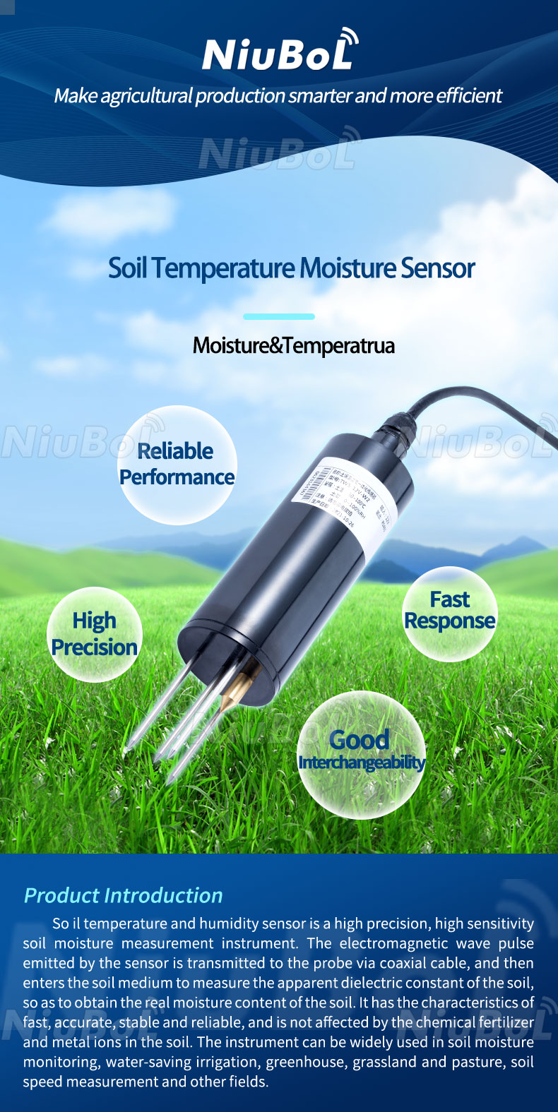
NBL-S-THR RS485 Soil Moisture & Temperature Sensor
Suitable for agriculture, irrigation, greenhouse and IoT monitoring. The RS485 Modbus version can connect to PLCs, RTUs and data loggers and can share a bus with other uniquely addressed Modbus sensors.
View Product →
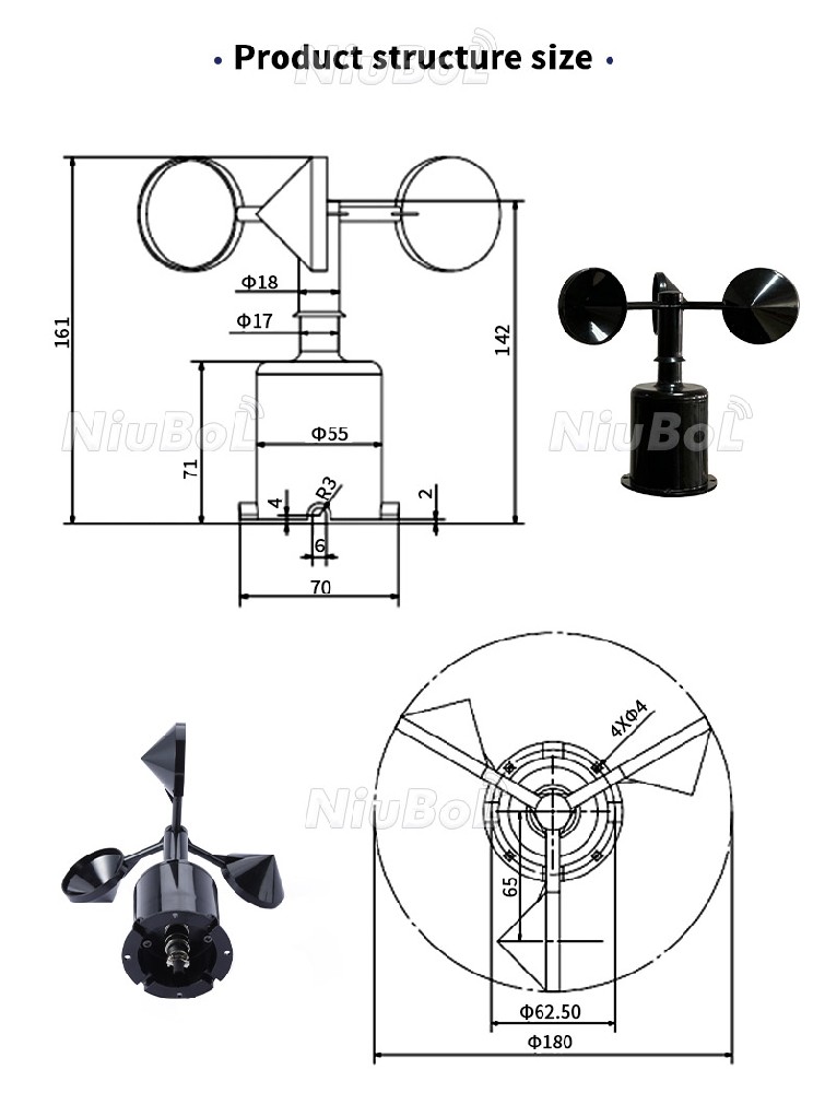
NBL-W-SS RS485 Wind Speed Sensor
An example of an environmental sensor that can provide RS485 Modbus output for integration with weather stations, PLCs and data-acquisition systems.
View Product →
To connect an RS485 Modbus sensor to a PLC:
Confirm the sensor power supply.
Connect RS485 A/B correctly.
Confirm sensor Modbus address.
Confirm baud rate, parity and stop bits.
Obtain the Modbus register map.
Configure the PLC as Modbus RTU master/client.
Read the required registers.
Apply the scaling factor specified by the manufacturer.
Sensor → RS485 Modbus RTU → PLC → HMI / SCADA
For remote monitoring, an RS485 sensor can connect to a 4G, Ethernet or LoRaWAN gateway.
RS485 Sensor → IoT Gateway → 4G / Ethernet / LoRaWAN → MQTT / HTTP → Cloud or Private Server
The gateway polls the Modbus registers and converts the measurement into a network protocol such as MQTT or HTTP.
| Problem | Likely Cause | Check |
|---|---|---|
| No response | A/B reversed, wrong address or no power | Power, polarity, address and serial settings |
| Intermittent data | Noise, topology or termination problem | Cable routing, shield, bus topology and termination |
| Wrong values | Wrong register or scaling | Register map, byte order and scaling factor |
| Only one device works | Duplicate addresses | Assign unique Modbus addresses |
| Remote sensor resets | Voltage drop | Measure supply voltage at the remote sensor |
A1. No. RS485 is an electrical serial communication standard. Modbus is a communication protocol. Modbus RTU commonly operates over RS485.
A2. Yes. RS485 can carry many different serial protocols. Modbus RTU is only one of the most common protocols used over RS485.
A3. Yes. Modbus RTU can operate over serial interfaces such as RS232 or RS485, while Modbus TCP operates over Ethernet/TCP-IP.
A4. The practical number depends on the RS485 transceivers, network loading, cable length and system design. Modbus addressing also requires every sensor to have a unique address. For larger networks, repeaters or segmented buses may be required.
A5. Yes, when multiple Modbus devices share one bus, each active device normally needs a unique slave/server address.
A6. Yes. A/B should normally use a twisted pair because twisting improves rejection of electromagnetic interference.
A7. It depends on cable length, baud rate and network design. For longer buses, approximately 120 Ω termination is commonly installed at the two physical ends of the bus, not at every device.
A8. Common causes include unsuitable cable, excessive baud rate, voltage drop, poor topology, missing termination, ground-potential differences and electromagnetic interference.
A9. Yes. An IoT gateway can read Modbus RTU registers through RS485 and convert the data into MQTT messages for transmission to a broker or private server.
A10. You need the sensor power requirement, A/B wiring definition, Modbus address, baud rate, parity, stop bits, function code, register map, data format and scaling factor.
NiuBoL provides RS485 Modbus sensors for weather, soil, agriculture, water quality, water level and environmental monitoring. Sensors can connect directly to PLCs, RTUs and data loggers or to IoT gateways for MQTT, HTTP and private-server integration.
For integration support, provide the sensor model, number of devices, cable distance, power supply, PLC or gateway model and required server protocol.
Related recommendations
Sensors & Weather Stations Catalog
 Agriculture Sensors and Weather Stations Catalog-NiuBoL.pdf
Weather Stations Catalog-NiuBoL.pdf
Agriculture Sensors Catalog-NiuBoL.pdf
Water Quality Sensor Catalog-NiuBoL.pdf
Related products
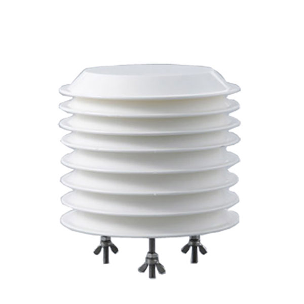 Combined air temperature and relative humidity sensor
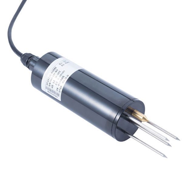 TDR Soil Moisture & Temperature Sensor for irrigation| RS485 |4-20mA| NBL-S-THR
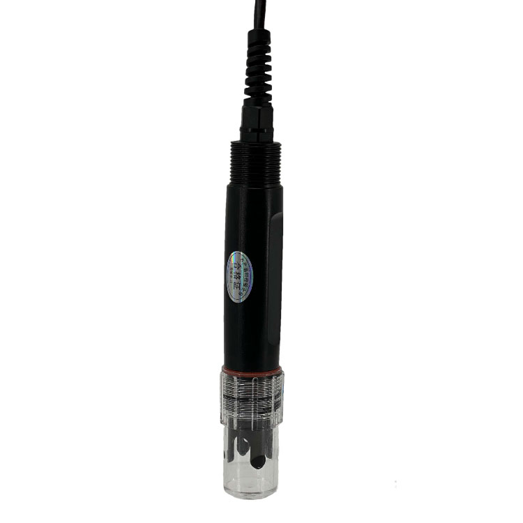 Soil pH sensor RS485 soil Testing instrument soil ph meter for agriculture |NBL-S-PH
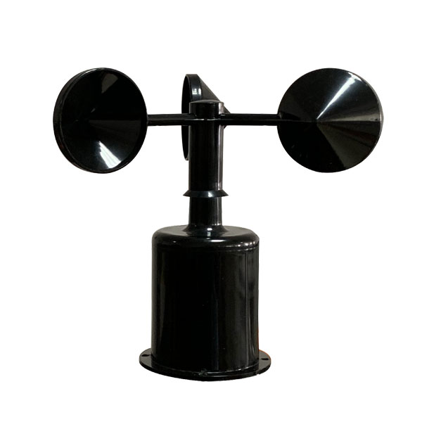 Wind Speed sensor Output Modbus/RS485/Analog/0-5V/4-20mA
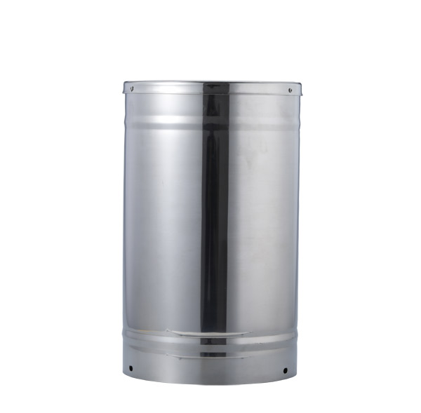 Tipping bucket rain gauge for weather monitoring auto rainfall sensor RS485/Outdoor/stainless steel
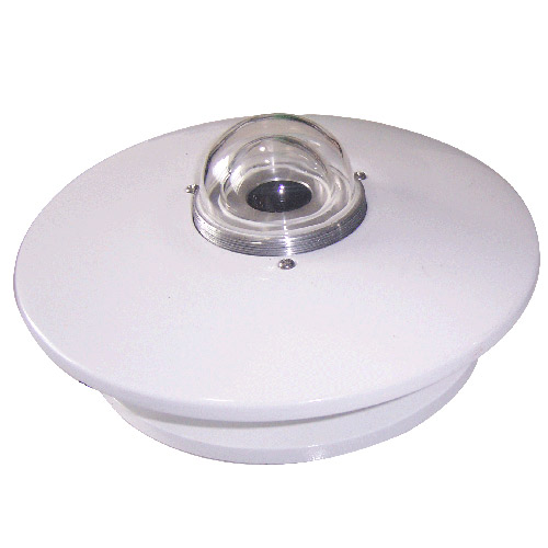 Pyranometer Solar Radiation Sensor 4-20mA/RS485

Screenshot, WhatsApp to identify the QR code
WhatsApp number:+8615367865107
(Click on WhatsApp to copy and add friends)