





— Blogs —
—Products—
 Consumer hotline +8618073152920
WhatsApp:+8615367865107
Address:Room 102, District D, Houhu Industrial Park, Yuelu District, Changsha City, Hunan Province, China
Product knowledge
Time:2026-02-03 14:39:05 Popularity:571
A railway automatic weather station should feed a railway operator's defined weather-risk workflow. It is not, by itself, a train-control or certified safety system. For a line exposed to crosswinds, fog, snow or heavy rain, the engineering questions are where the hazard occurs, which sensor observes it, how stale or failed readings are identified, and which existing system receives the data. NiuBoL can supply sensing equipment and compatible field interfaces; the operator and its approved integrator must specify the operational rules and acceptance evidence.
One line may include a bridge, exposed embankment, cutting, tunnel approach and shaded section within a short distance. Those locations do not share the same wind or visibility exposure. Mark known weather incidents and the operating sections they affect, then choose stations whose measurement footprints represent those sections. Do not calculate a station count from route length alone. A cabinet beside an easy access road may be unsuitable for a bridge-deck wind decision or a valley fog decision.
For each proposed site, record chainage, coordinates, ground and rail elevation, nearby structures, power and telecom access, maintenance route and the position of overhead electrical infrastructure. Establish with the railway owner where staff may work, whether an isolation or possession is needed, and how a mast or enclosure will be protected from passing vehicles and maintenance machinery. A station drawing must be reviewed against railway clearances and local design requirements before any bracket is fabricated.
The survey should also identify what the historical incident report actually describes. A wind complaint at a bridge may require exposure at deck height, while a station on the approach cutting may see a different flow regime. Repeated low visibility at a tunnel mouth can be a local aerosol or fog condition, not a route-wide event. If two sites are candidates, take temporary readings or operator observations during relevant weather before committing to permanent civil works. The added survey effort is small compared with deploying a permanent node that cannot support the intended operating decision.
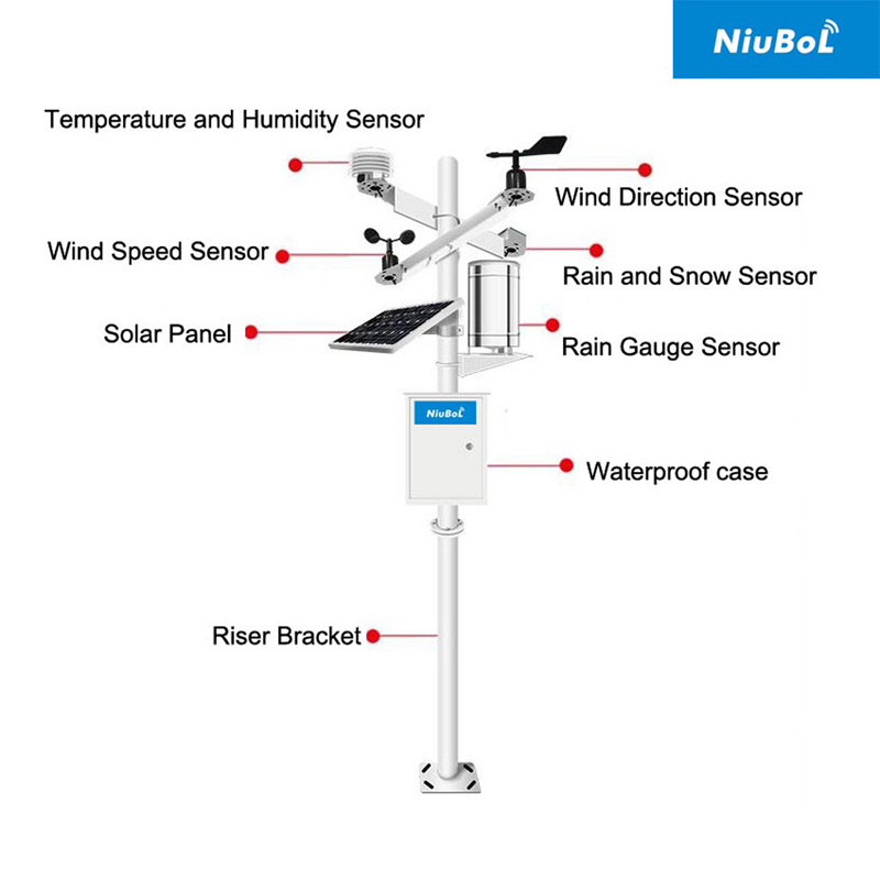
The first photograph shows a modular weather station arrangement. It is a component illustration, not a claim that every pictured channel is necessary or approved for a particular railway. Create a point list for the identified hazards first; then order the sensor variants and mounting details.
Wind speed and direction can support an exposed bridge or embankment assessment, but the sensor must be mounted at a representative location and its averaging or gust interval agreed with the operator. Visibility instruments estimate meteorological optical range near their sampling point. A fog pocket can be missed by a sensor on a clear ridge. Rain gauges and snow instruments describe precipitation or surface deposition at their positions; neither is a direct measurement of rail adhesion or track temperature.
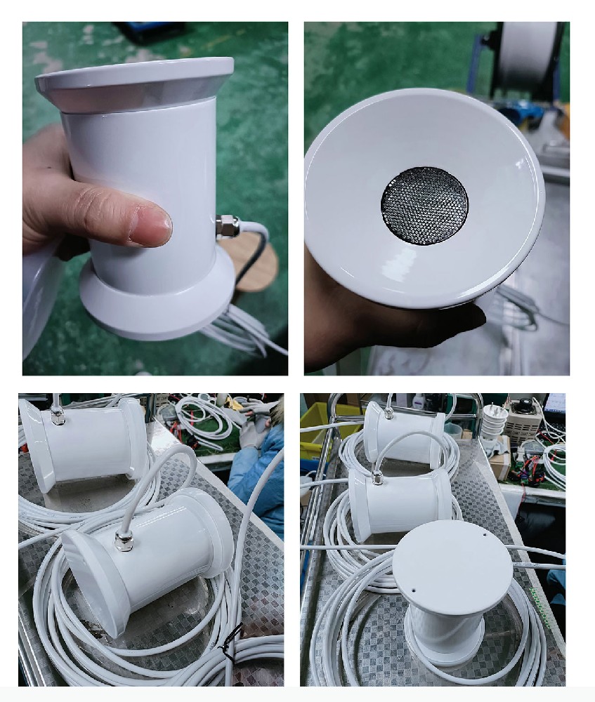
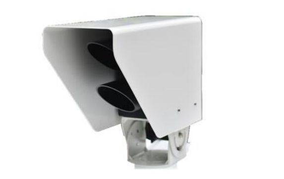
The snow instrument photograph illustrates an optional winter channel. Before procurement, distinguish snow depth, snow presence, precipitation and rail-surface temperature. They are different quantities with different mounting and cleaning needs. If the railway requires a rail temperature or condition input, request an instrument specifically evaluated for that measurement rather than attaching a road-surface sensor to the rail. The later photograph of a road-condition housing is useful as a reminder of this difference: its appearance does not establish railway suitability.
| Railway question | Potential observation | Boundary to define |
|---|---|---|
| Crosswind at an exposed structure | Wind speed and direction at a representative point | Mounting height, averaging, gust and failed-data treatment |
| Fog near a route segment | Local optical visibility | Fog variability, optical cleaning and represented chainage |
| Precipitation affecting drainage | Rainfall plus water-level or drainage data where needed | Rain at a station does not prove water on the track |
| Winter exposure | Snow, air conditions and a separate rail-related measurement if required | Do not substitute a road-surface device without validation |
At the field layer, selected NiuBoL sensors can connect to a compatible logger or RTU through the output ordered for that model. For an RS485 Modbus RTU device, confirm address, baud rate, register, data type, unit and error value with the product documentation. The NBL-W-VS visibility sensor is one example of a forward-scattering optical instrument with an RS485 interface. A different gauge or wind model may use another signal option; do not assume every sensor on the mast has the same four-wire pinout.
At the remote layer, the logger needs a configured communications service and a receiving endpoint. Fiber, cellular and local network options depend on the project equipment and railway IT requirements. Redundancy is not a standard property of the sensing head. Define which point values must be stored during a link outage, how clocks are synchronized, what is retransmitted after recovery and how the operator sees a stale observation. A missing wind message should not silently appear as calm weather.
At the operational layer, the railway authority determines alarms and any traffic response under its own rules. A supplier-provided sensor value is an input, not permission to command a speed restriction. The integrator should map station IDs to chainage and control zones, apply agreed plausibility and fault logic, and record who can acknowledge an alarm or override a suspect instrument.
Data retention should support investigation, not only live display. Preserve the raw value, its sample time, sensor-health state and any calculated interval value separately. A high wind value averaged over an hour does not answer a question about a short gust unless the sensor and logger captured that event. Likewise, a visibility average can hide a brief fog episode. Ask the operator what temporal resolution is needed for both immediate response and later review, then verify that the instrument, logger, link and database preserve it end to end.
Mount the mast and enclosure so routine inspection can be done under an approved safe-work arrangement. Keep optics accessible for cleaning and wind heads reachable for inspection without improvising work near live railway equipment. Confirm structural loading from the actual sensor arms, panel and enclosure. Cable glands, drip loops and protected routes matter as much as a sensor's housing rating. Surge and grounding provisions need a design consistent with the railway site and its electrical rules.
Where only solar power is available, calculate consumption from sensors, logger, communications and any heaters using their actual duty cycles and the local solar resource. Do not quote a fixed number of autonomous days from a standard package. A visibility head with an optional heater or a frequently transmitting modem can change the power budget materially. The site owner should also decide who changes batteries and how a low-voltage alarm reaches maintenance staff.
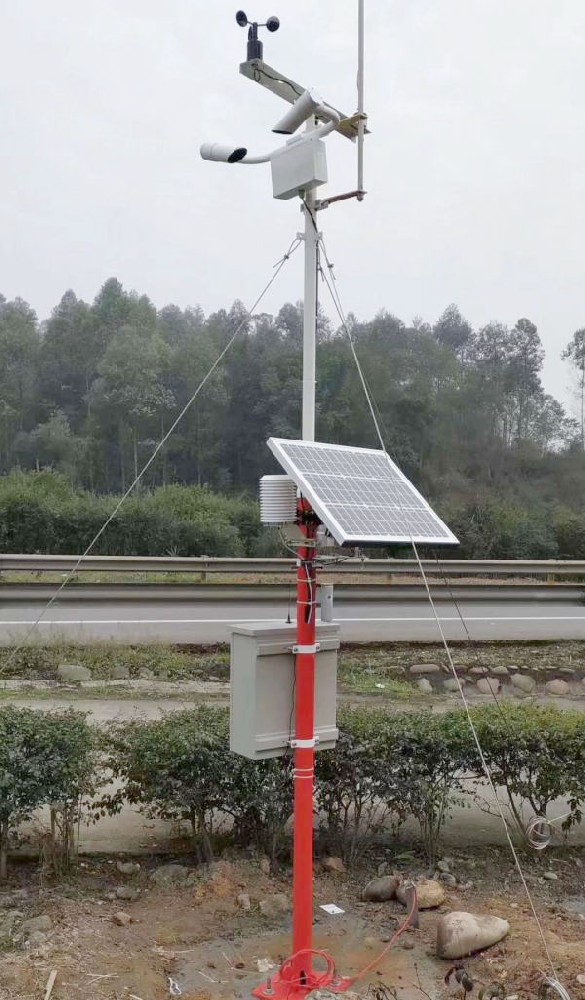
The roadside weather-station photograph is an example of sensor mounting, not an as-built railway installation. In a rail project, the location, clearance and data integration must be checked against the railway's drawings. Do not copy a road station's mast position or warning thresholds onto a rail corridor.
At commissioning, compare each sensor value at the head or logger with the value shown in the receiving system. Confirm unit, timestamp, station ID, physical location and configured measurement interval. Check wind orientation against a known bearing, inspect the visibility optics and verify a controlled rain-gauge count if rainfall is installed. A clear-weather acceptance test can establish the data path, but it cannot prove that a fog point represents every fog event; plan review during the first relevant weather period.
Simulate a sensor disconnection, local power failure and wide-area communications loss under the operator's test procedure. Verify the receiving system flags missing or old values and that recovery does not create duplicate or out-of-order records. If alarms are commissioned, use an approved simulated input, not an unsafe trackside condition. Keep the station drawings, register map, test results, maintenance procedure and responsibility matrix in the handover package.
For a quotation, separate meteorological sensors, mast and civil work, power, enclosure, logger, telecom equipment, platform mapping and supervised commissioning. Identify what the railway owner will supply, such as permits, fiber access or a central alarm system. This prevents a sensor-only price from being mistaken for a fully accepted route monitoring node.
No. It provides observations. Any operational command needs the railway authority's approved rules, integration, supervision and safety process.
Do not assume so. A road-surface housing and a rail-related temperature or condition measurement have different mechanical and measurement requirements. Specify and validate the rail application separately.
Use route hazards and representativeness, not a universal spacing. Bridges, valleys, cuttings and shaded sections may need different observations even when they are close together.
No. RS485 Modbus RTU is a local device interface. The logger, remote network, central software and any redundancy are separate scope.
The receiver should mark that point invalid or stale, retain the last good timestamp and notify the responsible operator or maintainer as specified. It must not interpret no response as zero wind or clear visibility.
Provide as-built coordinates and chainage, sensor models and heights, electrical and register drawings, communications configuration, supervised fault-test results and the safe maintenance method.
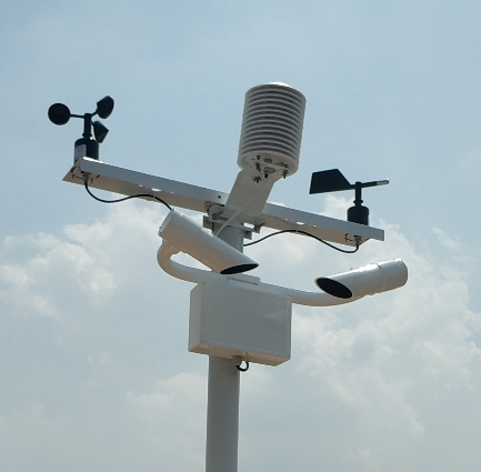
A railway automatic weather station is useful when its measurements represent named route hazards and arrive with traceable quality at the operator's system. Select the NiuBoL sensor layer against a surveyed site and an approved point list, then verify the data path and fault behavior. Railway operational decisions remain with the authority and its qualified integrator.
Prev:Agricultural Weather Station Model Inputs: Units and Exposure
Next:Residual Chlorine Monitoring After a Water Supply Shutdown
Related recommendations
Sensors & Weather Stations Catalog
 Agriculture Sensors and Weather Stations Catalog-NiuBoL.pdf
Weather Stations Catalog-NiuBoL.pdf
Agriculture Sensors Catalog-NiuBoL.pdf
Water Quality Sensor Catalog-NiuBoL.pdf
Related products
 Combined air temperature and relative humidity sensor
 TDR Soil Moisture & Temperature Sensor for irrigation| RS485 |4-20mA| NBL-S-THR
 Soil pH sensor RS485 soil Testing instrument soil ph meter for agriculture |NBL-S-PH
 Wind Speed sensor Output Modbus/RS485/Analog/0-5V/4-20mA
 Tipping bucket rain gauge for weather monitoring auto rainfall sensor RS485/Outdoor/stainless steel
 Pyranometer Solar Radiation Sensor 4-20mA/RS485


Screenshot, WhatsApp to identify the QR code
WhatsApp number:+8615367865107
(Click on WhatsApp to copy and add friends)

