





— Blogs —
—Products—
 Consumer hotline +8618073152920
WhatsApp:+8615367865107
Address:Room 102, District D, Houhu Industrial Park, Yuelu District, Changsha City, Hunan Province, China
Product knowledge
Time:2026-01-17 11:09:27 Popularity:645
Submersible level meter troubleshooting should separate a real water-level change from a pressure-reference, mounting, power or data-conversion fault. Recalibrating first can hide the original problem and create a new offset. For a NiuBoL hydrostatic installation, compare an independent level reference with the local reading, raw output and receiving-system value before changing the accepted span or zero.
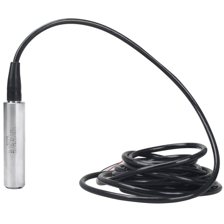
Record whether the reading is offset, slowly drifting, frozen, noisy or missing. Note when the behaviour began and whether it follows pumping, weather, cleaning or a configuration change. Keep the measurement timestamp with the value. A flat line with a frozen acquisition time is a different problem from a fresh sequence of identical raw readings.
Compare an independent reference at the same location and datum. A tank sight gauge, surveyed water-level observation or suitable portable reference can help, provided the physical comparison is valid. Do not compare pressure-derived height above a probe with depth below ground or a different tank's level and then adjust the offset to remove the apparent disagreement.
| Symptom | Initial checks | Do not assume |
|---|---|---|
| Constant difference | Probe elevation, reference zero, configured offset and unit conversion. | That a stable offset proves sensor drift. |
| Weather-related change | Independent water level and the vented pressure-reference path. | That every atmospheric correlation is a calibration error. |
| Change during pump operation | Local hydraulic disturbance and supply voltage under load. | That smoothing will fix either cause. |
| Flat or missing series | Last-good timestamp, local output, acquisition and communications. | That a connected gateway proves the probe is measuring. |
| Change after service | Reinstalled elevation, cable condition and accepted settings. | That the same sensor address means the same physical observation. |
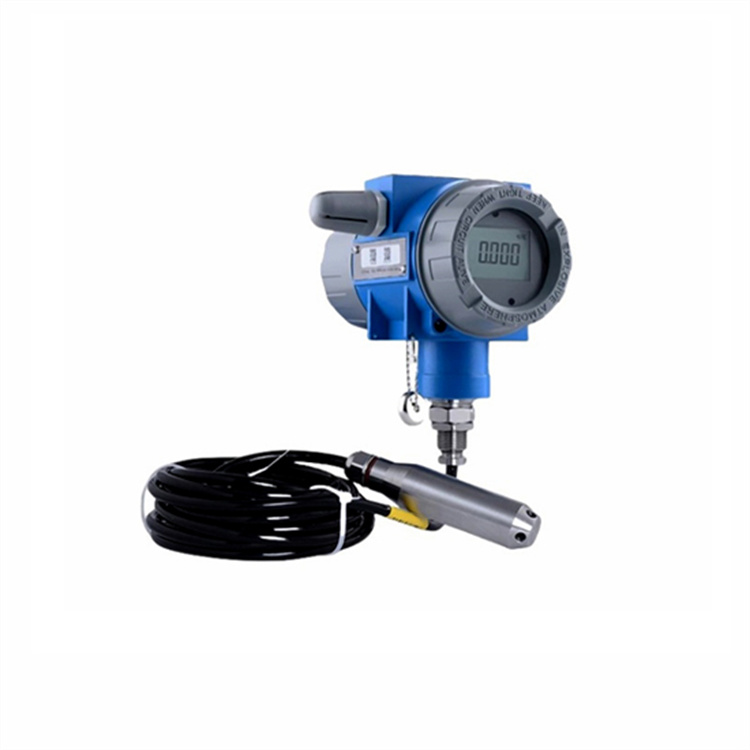
A vented gauge-pressure instrument needs its reference side connected to the intended atmospheric pressure. Water, condensation, crushed cable or an improperly sealed termination can interfere with that reference. Inspect accessible routing and the approved dry termination arrangement before applying a software correction. Do not force air, sharp tools or improvised sealants into a delicate reference path.
For scale, a 1 kPa pressure difference corresponds to approximately 0.102 m of freshwater head using density 1,000 kg/m3 and gravity 9.81 m/s2. This illustrates why a pressure-reference fault can produce a material level error; it is not a rule for subtracting weather data from every record. Establish the actual fault before correcting an affected series.
Keep a comparison through a relevant pressure or operating change where feasible. If the independent water level remains stable while the probe shifts, investigate the reference and instrument condition. If both move together, the level change may be real. A vent issue and a real water change can also coexist, so retain the observations needed to distinguish them.
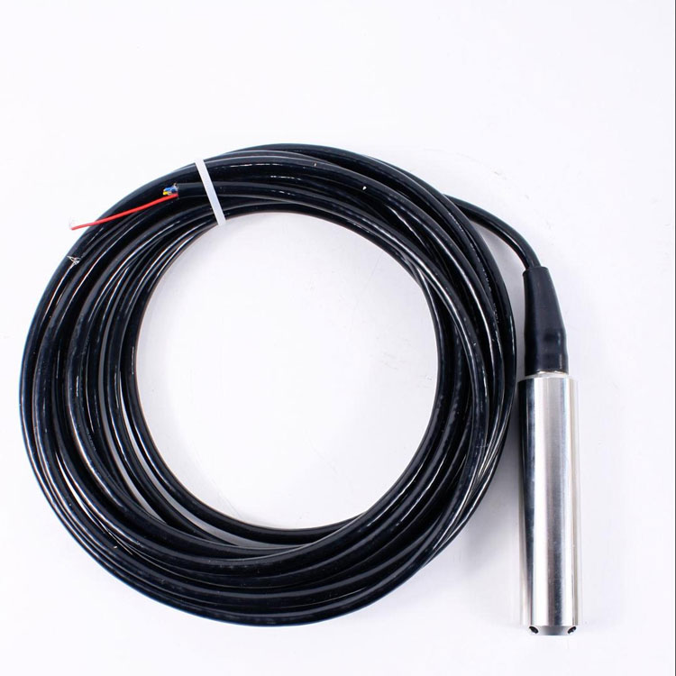
A pressure inlet near a pump intake, jet or strong local current may not represent the intended static head. Observe the local flow and compare a more representative reference point. A protective sleeve can reduce some disturbance, but its openings and response need to suit the application. A blocked or poorly connected sleeve may delay level response instead of improving it.
Check supply voltage at the instrument during pumping and communications events. A shared supply can dip when a motor circuit or radio load changes. The symptom may appear as a reset, missing replies or implausible readings. Voltage measured in an idle cabinet does not establish the conditions at the end of a long cable under peak demand.
For RS485, inspect wiring, address conflicts, serial settings and the installed bus arrangement. For an analog split transmitter, compare the actual loop current with the receiving input. The NiuBoL SMP4601 uses a 4-20 mA arrangement; it should not be diagnosed as though it exposes the same registers as a digital probe.
| RS485 NBL-L-WLPS configuration | Specification | Diagnostic use |
|---|---|---|
| Supply | DC 10-30 V, typical 24 V | Check remote-end voltage and transients, not only nominal supply. |
| Maximum power | 0.2 W | Keep probe consumption separate from the logger and radio. |
| Accuracy options | 0.5% FS default; 0.2% FS option | Evaluate the selected span and actual reference uncertainty. |
| Long-term stability | +/-0.2% FS/year | A stability specification is not a promise of zero drift or a universal service interval. |
| Circuit and medium limits | -20 to 80 degrees C circuit; long-term medium at or below 60 degrees C | Confirm the delivered version and actual exposure separately. |
| Interface and probe protection | RS485 Modbus RTU; IP68 probe | Verify mapping and accessible connections without treating all joints as submersible. |
The NiuBoL submersible transmitter measures hydrostatic pressure with a vented reference in this configuration. It is not a 77 GHz radar instrument. Wireless upload, local storage and a separate display depend on other selected components; faults in those functions should not automatically be attributed to the pressure probe.
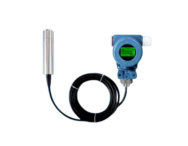
Read the local raw output through an approved service method and compare it with the logger. For a digital measurement with three decimal places, raw 101 represents 0.101 in the assigned unit, not 101. Confirm the actual scaling and numeric format before changing calibration. A decimal mistake can look like a sensor with an unsuitable range.
Where safe service conditions permit, observe a controlled change using a known reference. If the raw reading changes while the server value remains flat, investigate acquisition, caching or platform mapping. If the raw measurement does not respond, examine the instrument's pressure exposure, inlet condition and configuration rather than assuming a radio fault.
A split-type field transmitter can add a useful comparison point when that assembly is supplied. Confirm its input and output path; a display may show a locally transformed value. Do not assume every housing uses the same protocol or is approved for the same service location.
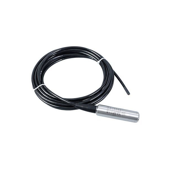
Inspect for sediment, fouling and mechanical damage using the approved service procedure. Do not probe the diaphragm or pressure inlet with a sharp object. Restore the sensor to its recorded elevation and secure the cable without carrying unsupported mechanical load through a vulnerable connection. Record a changed mounting position as a measurement change.
Check liquid composition and density if the process has changed. Sensor temperature compensation does not necessarily compensate changing fluid density. A density or headspace-pressure change can alter pressure-derived height even with sound electronics. Correct the interpretation only after confirming the physical process and which component owns the conversion.
Recalibrate when the verified instrument and reference comparison justify it after installation, reference and mapping faults have been excluded. Record pre-service and post-service values, settings and the validation result. For a replacement request, send NiuBoL the ordered model, range, liquid, wiring, raw observations and fault timeline. That evidence is more useful than a screenshot labelled inaccurate level.
No. Compare the reference, datum, pressure path, supply and acquisition first. Zeroing can conceal an installation or interpretation fault that reappears under another operating condition.
Inspect the modification for sealing, conductor and vent-reference effects. The original cable arrangement is part of the measurement system. Do not assume a mechanically tidy splice preserves its function.
Not by itself. Check current timestamps and raw response to an appropriate known change. A cached value or obstructed pressure path can also produce a flat graph.
It may smooth a signal while delaying real changes. First separate local hydraulics from electrical supply disturbance, then assess any filtering against the required event response.
No. Ingress protection does not establish a clear pressure inlet or prevent burial. Assess deposits, mounting and maintenance conditions separately.
Model and span, liquid and temperature, level reference, wiring and supply observations, raw/local/server comparisons and the time of recent service or settings changes. Include a clear fault timeline and the conditions that reproduce it.
Submersible level meter troubleshooting is most effective when each test separates pressure measurement from installation and data handling. Check the NiuBoL probe's reference path, operating conditions and raw response before adjusting its calibration. Restore a repeatable physical installation and verify the receiving record so the repair addresses the cause rather than making one graph look correct.
Prev:Wireless Level Monitoring System: Multi-Site Alarms and Service
Next:Submersible Level Transmitter Deep Well Installation: Range and Cable
Related recommendations
Sensors & Weather Stations Catalog
 Agriculture Sensors and Weather Stations Catalog-NiuBoL.pdf
Weather Stations Catalog-NiuBoL.pdf
Agriculture Sensors Catalog-NiuBoL.pdf
Water Quality Sensor Catalog-NiuBoL.pdf
Related products
 Combined air temperature and relative humidity sensor
 TDR Soil Moisture & Temperature Sensor for irrigation| RS485 |4-20mA| NBL-S-THR
 Soil pH sensor RS485 soil Testing instrument soil ph meter for agriculture |NBL-S-PH
 Wind Speed sensor Output Modbus/RS485/Analog/0-5V/4-20mA
 Tipping bucket rain gauge for weather monitoring auto rainfall sensor RS485/Outdoor/stainless steel
 Pyranometer Solar Radiation Sensor 4-20mA/RS485


Screenshot, WhatsApp to identify the QR code
WhatsApp number:+8615367865107
(Click on WhatsApp to copy and add friends)

