





— Blogs —
—Products—
 Consumer hotline +8618073152920
WhatsApp:+8615367865107
Address:Room 102, District D, Houhu Industrial Park, Yuelu District, Changsha City, Hunan Province, China
Product knowledge
Time:2026-01-17 11:14:59 Popularity:740
Submersible level transmitter deep well installation requires two separate depth calculations: the cable must reach the mounting position, while the pressure range must cover the largest water column above the probe. Confusing these dimensions can produce an expensive, oversized instrument or an overloaded sensor. For a NiuBoL NBL-L-WLPS installation, establish the well datum, highest water level and lowest pumping level before specifying the probe and cable.
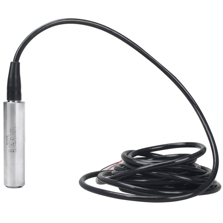
A well may extend far below the lowest water level that needs to be monitored. The probe does not automatically belong at the bottom. It needs to remain submerged at the lowest required measuring level, clear of accumulated sediment, with sufficient separation from pump intake turbulence. Its selected position also has to allow withdrawal without removing unrelated equipment.
Consider a proposed installation with the wellhead datum at zero, the probe at 35 m below that datum and the highest expected water surface at 5 m below it. The maximum water head at the probe is 30 m, not 35 m and not the total drilled depth. If the pumping water surface drops to 32 m below the datum, the probe still has 3 m of submergence. These are illustrative dimensions, not a recommended universal mounting depth or range.
The cable must cover the 35 m vertical route plus the actual path to the dry termination and a manageable service allowance. That cable length is a different order item from the pressure span. A project drawing should show both. Check foreseeable flood or recovery levels as well as normal operation when establishing maximum pressure.
| Well detail | Installation decision |
|---|---|
| Highest water surface | Sets the largest water head above the sensing diaphragm. |
| Lowest measuring level | Determines whether the selected probe position remains submerged. |
| Pump intake and discharge route | Identify turbulence, vibration and cable abrasion hazards. |
| Casing clearance | Check the probe, cable, support fittings and withdrawal route together. |
| Sediment depth | Keep the inlet above deposits and retain a way to inspect or recover it. |
| Wellhead to cabinet route | Add the real horizontal and vertical cable path, not just bore depth. |
Record depth to water from a repeatable reference mark. An unmarked tape reading from the edge of a removable cover will not give the next technician the same datum. If the required output is depth below wellhead, convert the measured head above the probe using the surveyed installation depth; do not label the raw head value as depth to water.
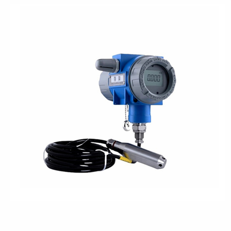
The NBL-L-WLPS RS485 configuration is a vented hydrostatic probe. A separate display transmitter, an analog loop instrument and a radio terminal are different assemblies. A photograph of a display head does not mean that display, battery or wireless service is included with the immersed RS485 probe.
| NBL-L-WLPS item | Specification and relevance |
|---|---|
| Measurement span | Specify the required water head when ordering; the range code identifies the selected span. |
| Accuracy grade | 0.5%FS standard; 0.2%FS configuration available. Evaluate the resulting error in metres. |
| Power | DC 10–30 V, typical 24 V; maximum consumption 0.2 W. |
| Communication | RS485, Modbus RTU for a compatible logger, RTU or PLC. |
| Probe size and protection | 26.8 mm outside diameter; IP68 probe protection. |
| Temperature | Transmitter circuit: -20 to 80°C; liquid at or below 60°C for long-term measurement. |
| Wetted components and cable | Stainless-steel probe and vented cable. Agree the exact material, jacket and supported length for the water chemistry and installation load. |
IP68 does not by itself state a universal permissible depth for every assembly. The selected pressure span, sealing arrangement and ordered cable length still matter. Neither the IP rating nor a stainless-steel housing establishes compatibility with hot geothermal water, saline groundwater or aggressive mine drainage.
Plan how the probe and cable loads will be carried before installation. Do not assume that any long signal cable is also a rated suspension rope. Ask for the allowable suspended load and the approved support method for the ordered cable. Where an independent support is needed, select fittings that do not obstruct the pressure inlet or create a snag during removal.
Route the cable away from sharp casing edges, pump power cables and moving equipment. Use suitable strain relief at the wellhead without flattening the cable or closing its internal vent tube. Leave an accessible identification label stating probe depth, range and cable destination. This prevents a later pump replacement from unknowingly changing the measurement datum.
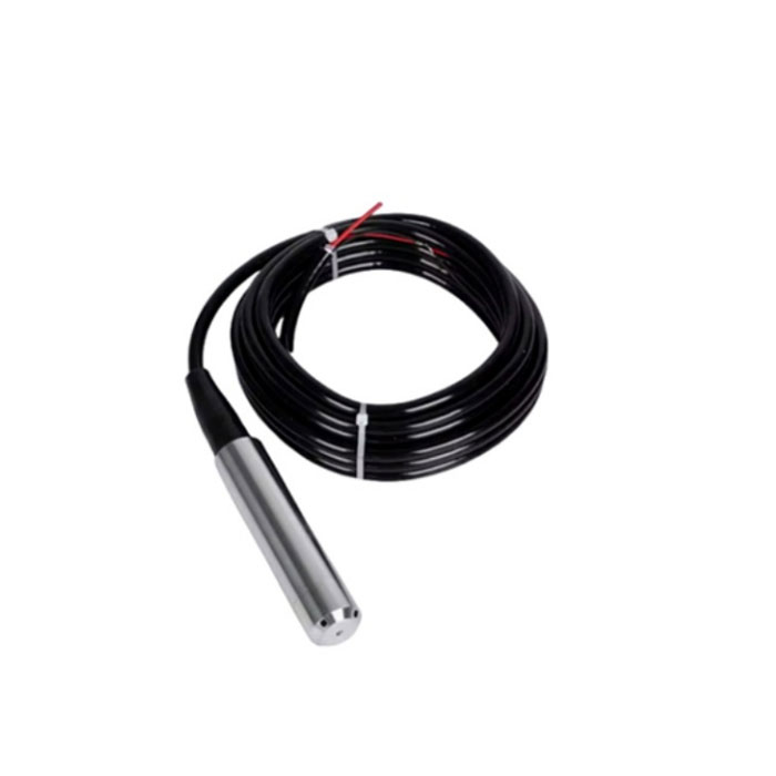
A protective tube can reduce lateral movement, but it must exchange water freely with the well at the relevant levels. A blocked or poorly perforated tube can make the sensor follow the water inside the tube rather than the well. Check response during pumping and recovery instead of accepting a quiet trace as proof of correct installation.
The vent connects the pressure reference to the atmosphere. Its dry end belongs in a protected termination arrangement that excludes rain, insects and condensation while preserving that reference. Potting or tightly sealing the vent opening can create a weather-dependent measurement error. An enclosure that is dry on installation day may still develop condensation later.
Where a moisture-control element is fitted, make it accessible for inspection and replacement. Avoid unapproved field splices: a splice must preserve the electrical connections, water seal and atmospheric path together. Ordering the correct cable length is usually simpler than trying to extend a vented assembly at the wellhead.
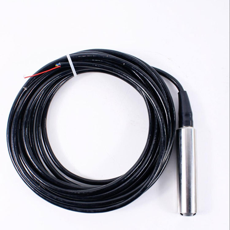
Measure voltage at the transmitter under its actual operating load, not only at an unloaded cabinet supply. Include the full cable route and any junctions in the voltage-drop assessment. RS485 is the communication interface; it does not supply probe power or make every cable topology suitable.
Configure the device address and serial settings locally before lowering the instrument. At the final logger, verify units and decimal scaling against the same raw register reading. If a remote gateway is required, test that function separately from the probe connection. A cloud timeout must not be mistaken for an empty well.
For a long well cable beside pump wiring, examine readings and communication errors with the pump both stopped and running. A stable bench connection is not sufficient evidence of field compatibility. Surge protection, grounding and shielding need to follow the site electrical design and the selected interface arrangement, rather than an assumed universal cable-distance claim.
After installation, record a static water-level reference, the corresponding sensor head and the probe elevation. Then compare the installed system during a controlled pumping change and recovery, where safe and permitted. The purpose is to find installation effects such as cable movement, intake pressure disturbance or a slow protective tube, not merely to obtain one matching value.
Keep the original observations before applying an offset. If agreement changes with pump operation, investigate the physical location and electrical conditions first. A zero correction cannot repair a moving probe, an obstructed vent or a range selected for the wrong maximum head.
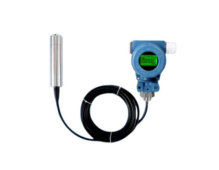
No. Range follows the greatest liquid head above the selected probe position. Total well depth and cable route are separate dimensions. Calculate the head at the highest expected water surface and check that the probe stays submerged at the lowest required level.
Do not assume this without a cable load rating and approved mounting detail. State the suspended length and support arrangement in the enquiry. Use an independent support where required without placing fittings across the inlet or damaging the vented jacket.
Not without checking the local pressure disturbance. Pump intake flow and vibration can affect a hydrostatic reading. Select an accessible, stable position and compare the response with an independent water-level reference during pumping and recovery.
The termination needs moisture protection, but the atmospheric vent must remain functional. Use a suitable protected vent arrangement rather than sealing every opening. Include access for checking moisture-control components.
Only after checking liquid temperature and every wetted material. The NBL-L-WLPS configuration described here has a long-term medium limit of 60°C. Supply the water analysis and temperature range before selecting a probe for aggressive or hotter water.
Provide the well reference drawing, expected high and low water levels, probe mounting depth, cable route, pump location, water chemistry, temperature and receiver interface. These determine the pressure span, cable and support scope more directly than the drilled depth alone.
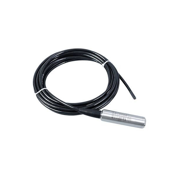
A deep-well installation is ready for specification when pressure span, suspended cable, atmospheric vent and measurement datum have each been defined. The NiuBoL submersible probe supplies the level signal; the installation must preserve its reference and position. Send the well geometry and operating levels with the enquiry so the offered assembly can be assessed as an installable system rather than a probe with an approximate cable length.
Prev:Submersible Level Meter Troubleshooting: Drift and Missing Data
Next:Submersible Level Meter Application Selection: Tanks, Wells and Rivers
Related recommendations
Sensors & Weather Stations Catalog
 Agriculture Sensors and Weather Stations Catalog-NiuBoL.pdf
Weather Stations Catalog-NiuBoL.pdf
Agriculture Sensors Catalog-NiuBoL.pdf
Water Quality Sensor Catalog-NiuBoL.pdf
Related products
 Combined air temperature and relative humidity sensor
 TDR Soil Moisture & Temperature Sensor for irrigation| RS485 |4-20mA| NBL-S-THR
 Soil pH sensor RS485 soil Testing instrument soil ph meter for agriculture |NBL-S-PH
 Wind Speed sensor Output Modbus/RS485/Analog/0-5V/4-20mA
 Tipping bucket rain gauge for weather monitoring auto rainfall sensor RS485/Outdoor/stainless steel
 Pyranometer Solar Radiation Sensor 4-20mA/RS485


Screenshot, WhatsApp to identify the QR code
WhatsApp number:+8615367865107
(Click on WhatsApp to copy and add friends)

