





— Blogs —
—Products—
 Consumer hotline +8618073152920
WhatsApp:+8615367865107
Address:Room 102, District D, Houhu Industrial Park, Yuelu District, Changsha City, Hunan Province, China
Product knowledge
Time:2025-11-24 16:58:47 Popularity:753
Ultrasonic compact weather station servicing should account for the shared sensor head as well as individual measurement channels. No rotating wind cups means fewer mechanical wear points, not maintenance-free operation. Before replacing a head, distinguish a measurement fault from power, cable or decoding problems. A replacement must match the required channels, output units, communication settings and mounting reference, and the change must remain visible in the measurement history.
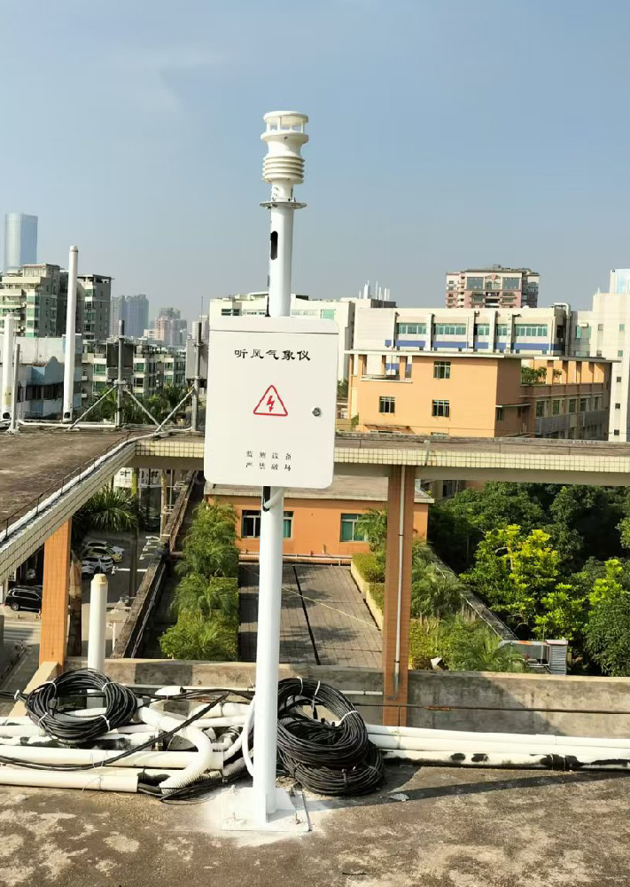
When all channels disappear together, inspect common causes such as the supply, shared cable and communication path. If only one channel becomes implausible while valid frames continue, examine its physical exposure and decoding. Neither symptom proves the head is defective. Retain the last valid records, the onset time and any status or error information before restarting equipment or changing settings.
A whole-head replacement can interrupt several measurements at once. Determine which functions depend on them before a service visit. A display outage and the loss of a controller input have different consequences. Any temporary control arrangement should follow the project's approved safety design, not be improvised by forcing stale or zero weather values into the receiving system.
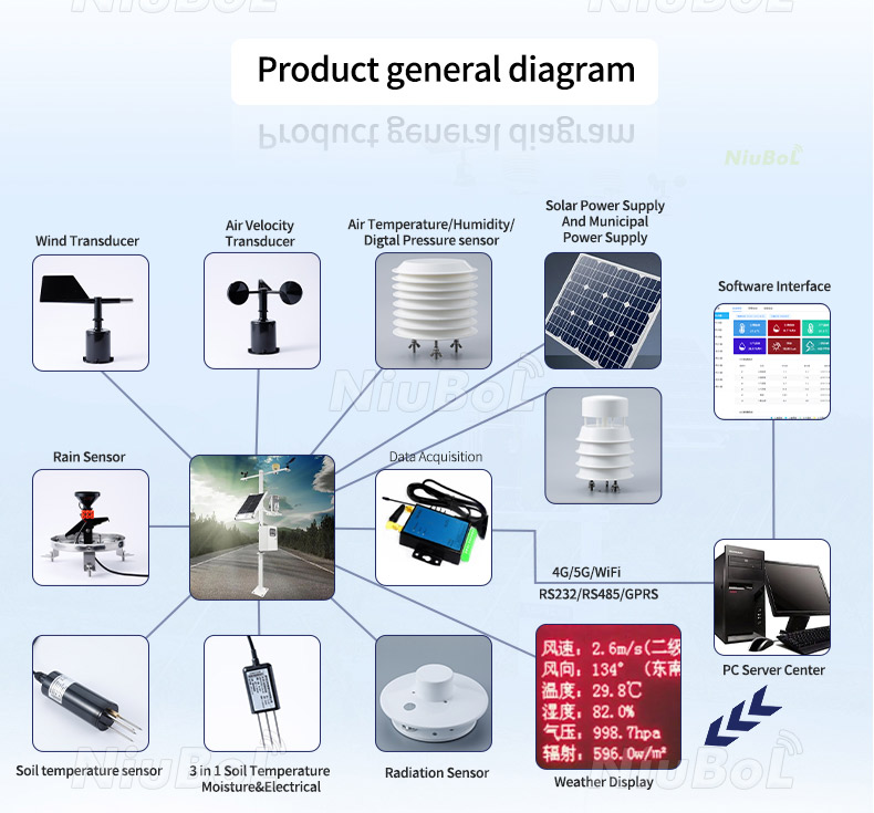
The head measures its configured quantities. A logger records values, a modem or gateway provides remote communication, and a power system supplies the installation. These are separate fault locations even if the equipment is sold as one station. A working modem does not prove the sensor is responding; a working sensor does not prove its history is reaching the customer's server.
Ask for a service diagram showing the head connector, supply, serial bus, logger input and remote path. It should identify accessible test points and isolation procedures. This lets a technician test the affected part without unnecessarily changing the logger, replacing unrelated sensors or losing stored observations.
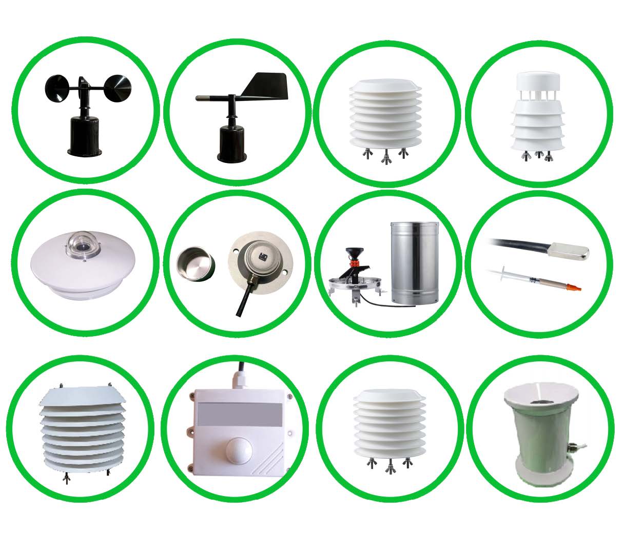
The NBL-W-71GUWS 7-in-1 sensor combines wind speed, direction, air temperature, relative humidity, pressure, piezoelectric rainfall and one selected light quantity. Solar irradiance and illuminance are alternative seventh channels in the listed configuration, not two channels delivered together. A replacement with Lux output is not equivalent to an irradiance version merely because the housing is the same.
| NBL-W-71GUWS item | Specification | Replacement check |
|---|---|---|
| Wind | 0-60 m/s; direction 0-359 degrees | Retain speed units and geographic direction reference |
| Rainfall | Piezoelectric detection; range 0-8 mm/min | Do not apply tipping-bucket pulse scaling |
| Selected light channel | 0-1500 W/m2 solar irradiance or 0-200000 Lux illuminance | Match the ordered quantity and its units |
| Interface | RS485 Modbus RTU; 9600 bps; minimum interval 1000 ms | Check address, register map and logger settings |
| Average consumption | 0.4 W | Head rating, not the complete station load |
| Protection | IP65 | Retain outdoor connector protection and mounting requirements |
Product names such as compact or all-in-one do not establish interchangeability. Record the old and replacement model, serial identity, configuration and applicable instructions. Where the register structure or firmware differs, validate the receiving software rather than relying on connector fit.
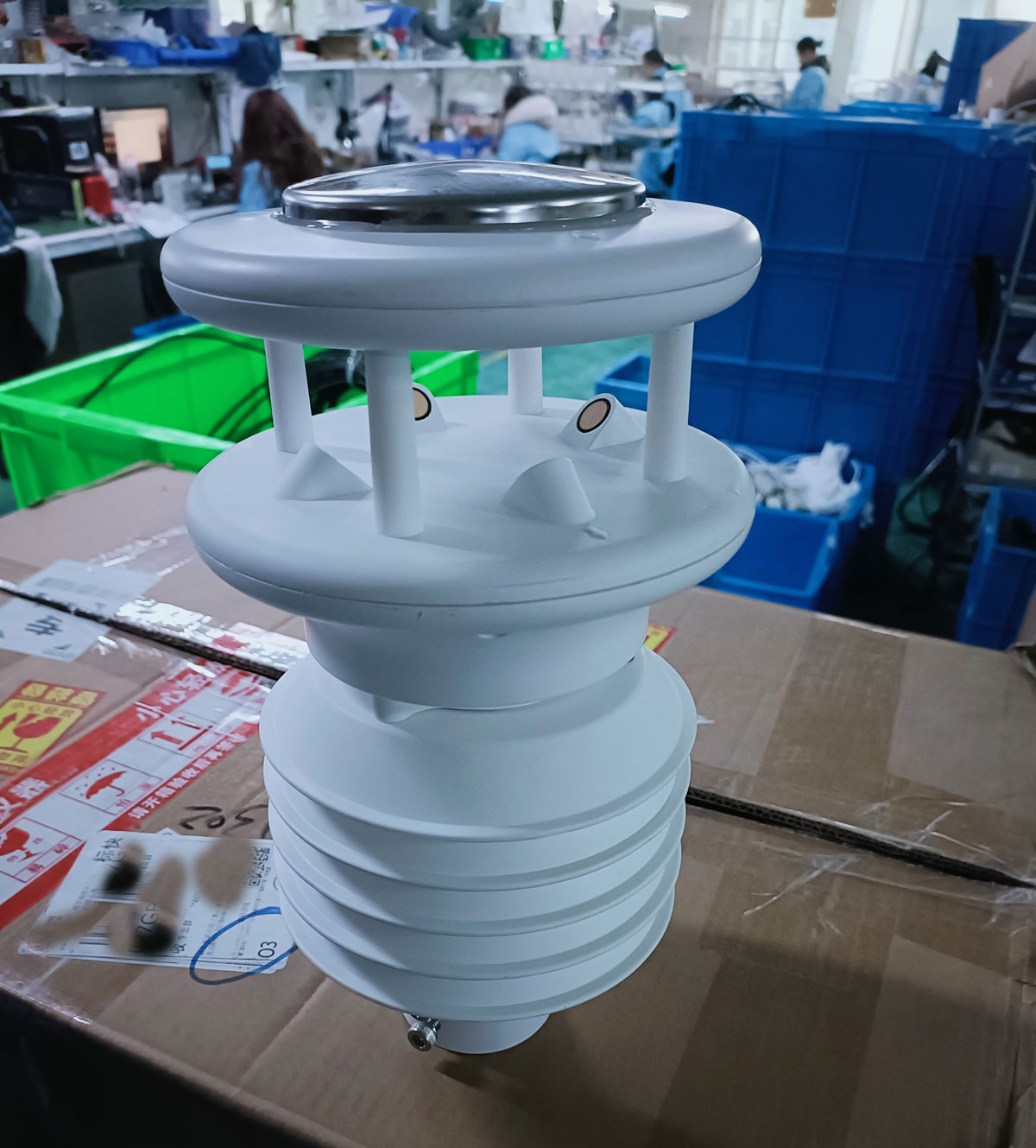
Ultrasonic wind depends on clear acoustic paths. Dirt, insects, ice or physical damage can interfere with measurement. Inspect the passages and supports using the appropriate cleaning method; do not bend transducers or scrape sensing surfaces to restore a plausible number. The lack of bearings does not remove the need to check exposure and contamination.
The other channels have different inspection needs. A piezoelectric rainfall surface is not a tipping bucket and should not receive a bucket calibration or lubrication procedure. Air measurement depends on suitable shield exposure. An optical surface can be affected by dirt or shadow. Treat each channel according to its actual sensing method rather than applying one generic cleaning routine.
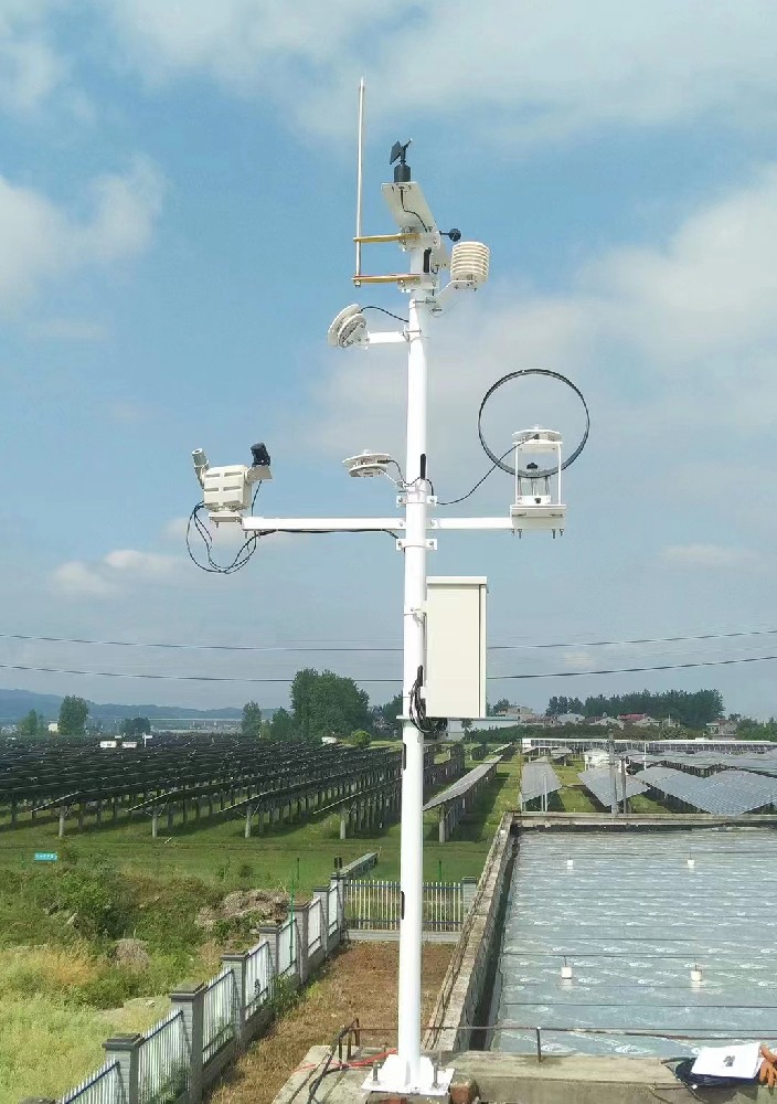
Where practical, connect the replacement to a suitable supply and compatible logger before transport. Verify response frames and decoded quantities. The NBL-W-71GUWS supply options are listed as DC 9-24 V or DC 12-24 V; use the approved range for the delivered version. Do not infer a pinout from cable color on a different model.
Use a configuration record to compare old and new channel mappings. For example, check whether rainfall is cumulative or rate data and how negative temperatures are decoded. A value that fits a display field is not proof of correct scaling. Keep unavailable optional registers out of normal dashboards instead of treating their values as valid measurements.
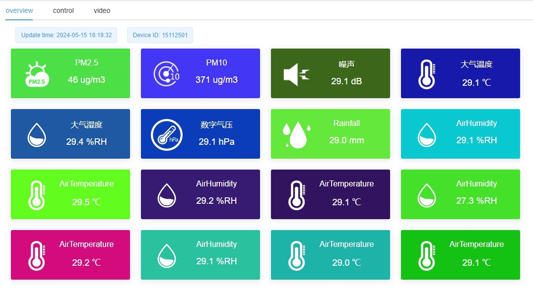
Install the head vertically and secure the mounting as specified. The NBL-W-71GUWS requires its north reference to be aligned with geographic north. Do not assume an electronic compass or automatic heading correction is included. Before removal, record the installed reference; after replacement, verify it rather than copying an unknown old offset.
Photograph the surrounding exposure and note changes in pole position, height or nearby structures. If the sensor is moved while being replaced, a shift in readings may reflect the new exposure as well as the new instrument. Keep those changes separate in the service record so later analysis does not mistake them for a weather trend.
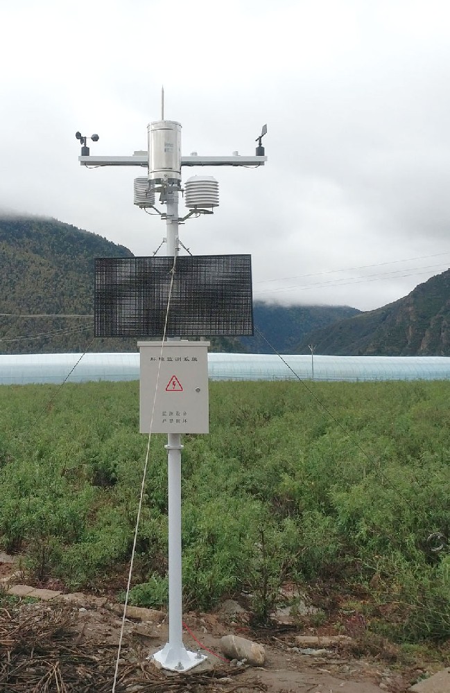
Record the removal and restart times, equipment identities, configuration changes and channels unavailable during the visit. Cumulative rainfall needs particular attention: a new device or reset can start a new accumulation period. Do not subtract the old counter from a new counter without a defined continuity rule. Service-generated test readings should be identified separately from field observations.
Before declaring the station returned to service, compare local decoding, logged values and remote display for every required channel. Confirm that new values have new observation times. Keep the original history and tag the replacement event; filling a gap with zeros conceals the interruption rather than repairing it.
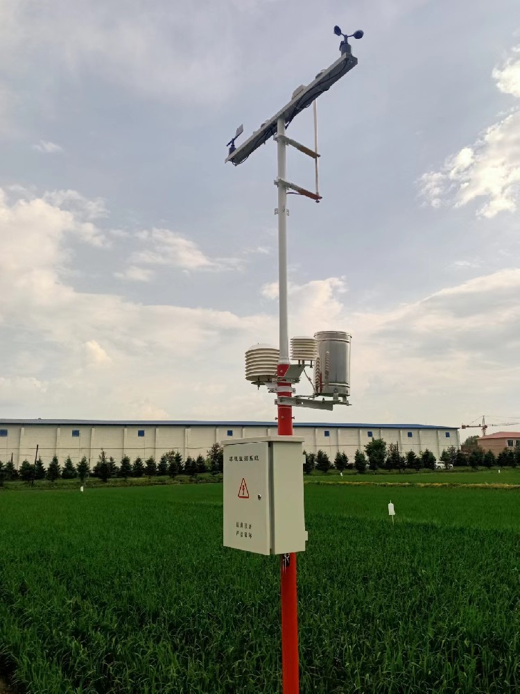
Not automatically. First check power, communication, decoding and the affected sensing surface. Repair or replacement scope depends on the actual fault and the model's available service options.
Only if the project deliberately accepts that change and updates the data system. Lux and W/m2 describe different quantities; matching the housing or connector is insufficient.
Yes for the NBL-W-71GUWS. Ultrasonic wind measurement does not provide geographic heading by itself. Point the marked reference toward geographic north as specified for the selected model.
Identify the exact replacement configuration, cable and mounting compatibility, site access, data interruption, configuration work and post-replacement checks. State whether a loan unit or spare is included rather than assuming one.
Not automatically. Check counter behavior and logger history separately, record the replacement time and retain a clear boundary between old and new accumulation periods.
Model-specific instructions
NBL-W-21GUWS ultrasonic wind speed and direction sensor instructions (PDF).
 NBL-W-21GUWS-Ultrasonic-Wind-speed-and-direction-Sensor.pdf
NBL-W-61MUWS ultrasonic weather station instructions (PDF).
NBL-W-61MUWS-Ultrasonic-Weather-Station-Instruction-Manual.pdfNBL-W-71MUWS micrometeorological sensor instructions (PDF).
NBL-W-71MUWS-Micrometeorological-Sensor-Operating-Instructions.pdfAll-in-one ultrasonic weather sensor instructions (PDF).
All-in-One-Ultrasonic-Weather-Sensor-Instruction-Manual.pdfUltrasonic compact weather station servicing should restore valid measurements, not merely an online indicator. Diagnose the fault location, match the spare configuration and restore the installation reference. Give NiuBoL the installed model, required channels, fault records and receiving-system details so the service or replacement scope can be defined accurately.
Prev:Weather Monitor vs Weather Station: Define the Equipment Scope
Next:Application and Impact of Automatic Weather Stations in Forestry
Related recommendations
Sensors & Weather Stations Catalog
Agriculture Sensors and Weather Stations Catalog-NiuBoL.pdf
Weather Stations Catalog-NiuBoL.pdf
Agriculture Sensors Catalog-NiuBoL.pdf
Water Quality Sensor Catalog-NiuBoL.pdf
Related products
 Combined air temperature and relative humidity sensor
 TDR Soil Moisture & Temperature Sensor for irrigation| RS485 |4-20mA| NBL-S-THR
 Soil pH sensor RS485 soil Testing instrument soil ph meter for agriculture |NBL-S-PH
 Wind Speed sensor Output Modbus/RS485/Analog/0-5V/4-20mA
 Tipping bucket rain gauge for weather monitoring auto rainfall sensor RS485/Outdoor/stainless steel
 Pyranometer Solar Radiation Sensor 4-20mA/RS485


Screenshot, WhatsApp to identify the QR code
WhatsApp number:+8615367865107
(Click on WhatsApp to copy and add friends)

