





— Blogs —
—Products—
 Consumer hotline +8618073152920
WhatsApp:+8615367865107
Address:Room 102, District D, Houhu Industrial Park, Yuelu District, Changsha City, Hunan Province, China
Product knowledge
Time:2025-10-29 16:18:03 Popularity:1249
Liquid level sensors for tank control should be selected according to the required decision: a continuous level record, a threshold indication, or both. A level transmitter provides a changing measurement; a level switch indicates a condition at its sensing point. Neither performs the complete pump-control or overflow-protection function without an appropriately designed receiving system.
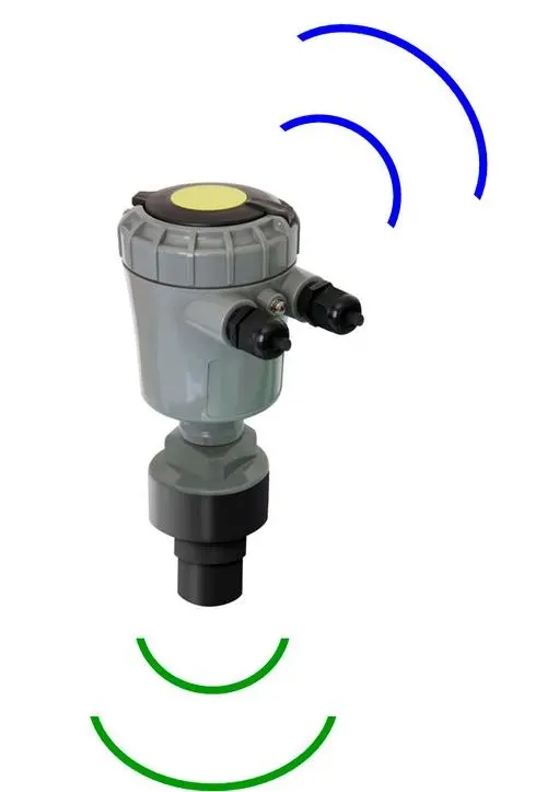
A tank operator may need to see remaining liquid, start replenishment within a selected band or identify an exceptional high level. These tasks do not always need the same instrument. A continuous transmitter supports trends and adjustable software thresholds. A point switch can provide a separate indication at a chosen height, but does not describe the full tank profile.
Before comparing ultrasonic, radar, hydrostatic or float arrangements, state the required output and operating action. The tank liquid, pressure, temperature and internal geometry then determine which measurement methods are suitable. There is no universal accuracy or material package for all liquid level sensors.
| Tank task | Information needed | Instrument distinction |
|---|---|---|
| Show level over time | A continuous value with units and a reference | Transmitter rather than a single point switch |
| Indicate a selected high or low condition | State at a defined sensing position or configured threshold | Point switch or validated transmitter-based logic |
| Estimate inventory | Level plus appropriate tank geometry | Level alone is not automatically volume |
| Provide an independent protective function | A separately assessed detection and response path | Two displayed channels do not by themselves establish independence |
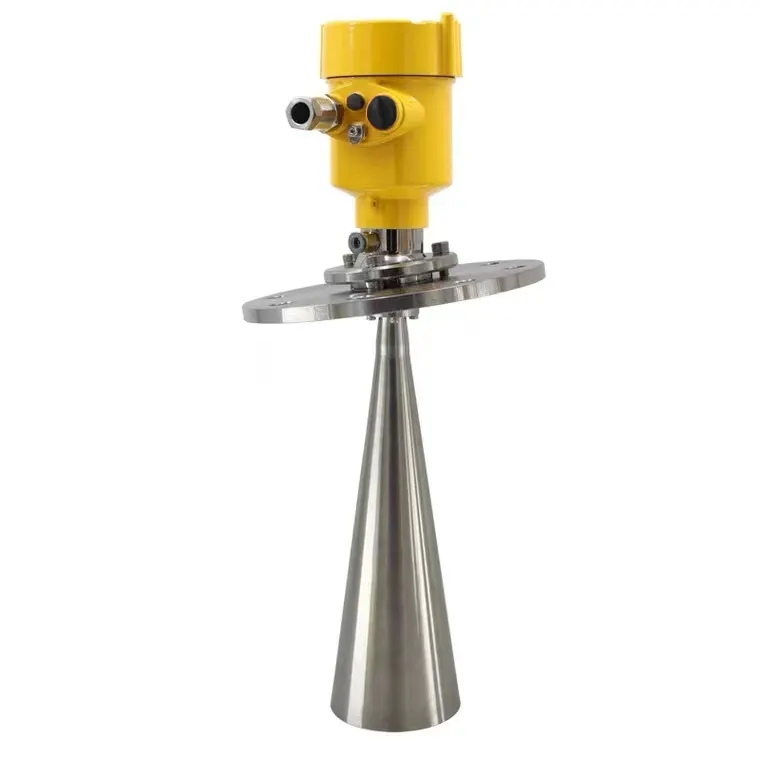
An ultrasonic instrument measures a sound travel path to the surface. A radar instrument uses electromagnetic waves. Select the actual model against the headspace, foam, condensation, internal obstructions and required near-surface clearance. Non-contact does not automatically mean suitable for every corrosive, pressurized or high-temperature vessel.
For a top-mounted instrument, record the reference distance and highest permitted liquid position. Check the proposed beam path against inlet streams, ladders and agitators. If the transmitter reads distance rather than level, apply the correct reference conversion in the receiving system. A decreasing distance can mean a rising level.
A hydrostatic instrument derives depth from liquid pressure. Its conversion depends on density and the pressure reference. A water-calibrated depth must not be treated as an unchanged depth for another liquid with a different density. In a pressurized tank, headspace pressure can also contribute to the measurement and needs an appropriate measurement arrangement.
Volume requires a relationship between level and tank geometry. A vertical cylinder and a horizontal cylinder have different level-to-volume relationships. Do not apply a linear percentage-to-volume conversion to an irregular tank without an appropriate capacity relationship.
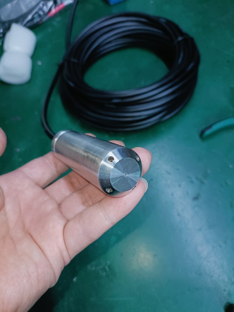
The NiuBoL NBL-L-WLPS submersible transmitter uses hydrostatic pressure measurement and RS485 Modbus RTU output. Select its range against the expected depth above the sensing diaphragm. It is intended for liquids compatible with its wetted materials, not every acid, solvent or hot process fluid.
| NBL-L-WLPS item | Specification or selection | Practical meaning |
|---|---|---|
| Measurement range | Selected to project requirements | State minimum and maximum depth, not only tank height |
| Supply / maximum power | DC 10-30 V / 0.2 W | Check the field supply at the probe connection |
| Interface / default baud rate | RS485 Modbus RTU / 4800 bps | Match master settings and the actual register format |
| Protection | IP68 probe | Protect the above-water cable termination separately |
| Reference arrangement | Vented cable | Keep the atmospheric reference path clear and dry |
| Long-term medium temperature | ≤60 C | Check liquid temperature independently of sensor-element limits |
Secure the probe so its reference position does not change with water movement. Keep the pressure opening clear of sediment and protect the diaphragm during installation. Do not crush or seal the cable's vent path. An IP68 probe does not make its atmospheric vent outlet suitable for immersion.
Liquid level sensors for tank control feed a PLC, RTU or other appropriate controller. Define the action for each operating state. A transfer pump supplying another tank and a sump pump removing water may need opposite responses to the same high-level indication. Generic instructions such as starting a pump whenever level is low are therefore unsafe to apply without the process context.
Use appropriate start and stop thresholds to avoid repeated switching around one value, and assess what should happen when the measurement is unavailable. A stale last value is different from a confirmed steady level. Define fault indication and local response before relying on a remote screen.
Where an independent overfill or dry-run protective function is required, have the responsible engineer define its architecture and validation. A second sensor sharing the same power, controller and final actuator may still share important failure modes. No safety rating should be inferred from the number of installed probes.

It can serve a threshold task if suitable for that application, but it cannot provide the same continuous level record or inventory calculation. State which information the receiving system actually needs.
Only after checking the exact instrument's material compatibility, density conversion and operating conditions. A water-level reading is not automatically valid for oil at the same depth.
No. A pressurized headspace changes the pressure arrangement. Review the tank pressure and required reference method rather than assuming an atmospheric-reference installation is adequate.
A digital level transmitter supplies data to a compatible controller. Pump switching requires appropriate logic, output equipment and protection. Do not connect a communication output as though it were a pump power contact.
Provide liquid composition, density if relevant, temperature, headspace pressure, tank geometry, desired range and control task. Include cable length and the receiving PLC or logger so the measurement and interface can be reviewed together.
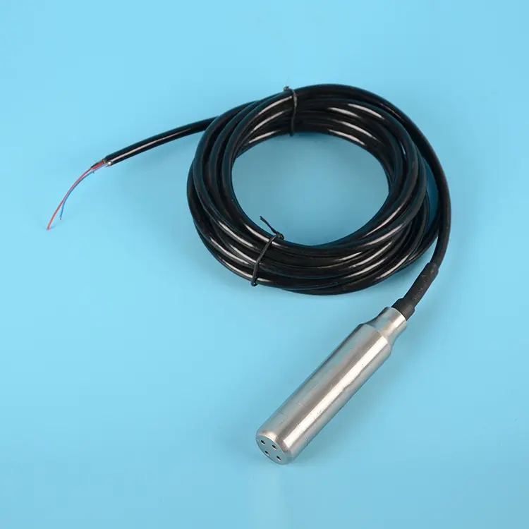
Choose liquid level sensors for tank control by separating continuous measurement, threshold indication and protective functions. Then match the measurement principle to the vessel and liquid. NiuBoL can review a compatible level-transmitter arrangement when the process conditions and receiving equipment are clearly defined.
Prev:Water Leak Detection Sensors: Cable Zones, Placement and Alarm Tests
Next:Dissolved Oxygen Meters: Principles, Calibration and Uses
Related recommendations
Sensors & Weather Stations Catalog
 Agriculture Sensors and Weather Stations Catalog-NiuBoL.pdf
Weather Stations Catalog-NiuBoL.pdf
Agriculture Sensors Catalog-NiuBoL.pdf
Water Quality Sensor Catalog-NiuBoL.pdf
Related products
 Combined air temperature and relative humidity sensor
 TDR Soil Moisture & Temperature Sensor for irrigation| RS485 |4-20mA| NBL-S-THR
 Soil pH sensor RS485 soil Testing instrument soil ph meter for agriculture |NBL-S-PH
 Wind Speed sensor Output Modbus/RS485/Analog/0-5V/4-20mA
 Tipping bucket rain gauge for weather monitoring auto rainfall sensor RS485/Outdoor/stainless steel
 Pyranometer Solar Radiation Sensor 4-20mA/RS485


Screenshot, WhatsApp to identify the QR code
WhatsApp number:+8615367865107
(Click on WhatsApp to copy and add friends)

