


— Blogs —
—Products—
 Consumer hotline +8618073152920
WhatsApp:+8615367865107
Address:Room 102, District D, Houhu Industrial Park, Yuelu District, Changsha City, Hunan Province, China
Product knowledge
Time:2025-10-29 16:09:20 Popularity:1223
Water leak detection sensors identify liquid reaching a sensing point or cable. They do not necessarily identify the broken pipe or prevent damage by themselves. For server rooms, HVAC areas and industrial equipment, start with likely water paths, divide the installation into useful zones, and test the complete alarm path rather than relying on an unsupported sensitivity or response-time claim.
A detector placed beside a pipe may remain dry while a leak follows the pipe insulation, a tray or a floor slope in another direction. Walk the potential water path from the source toward the equipment being protected. Look for joints, condensate drains, drip trays, low points and barriers that may divert a small release.
For a spot detector, the expected water must reach that spot. A sensing cable extends the exposed detection path, but a cable at the room perimeter does not guarantee detection beneath every cabinet. Floor voids and separate drainage compartments may need distinct routes. Avoid specifying coverage only as room area without showing how liquid can reach the detector.
| Arrangement | Useful task | Question to resolve |
|---|---|---|
| Spot detector | A known low point or small collection tray | Will the first relevant water reach the sensing surface? |
| Cable detector with zone alarm | A routed path around equipment or along a risk boundary | Can staff inspect that zone quickly enough? |
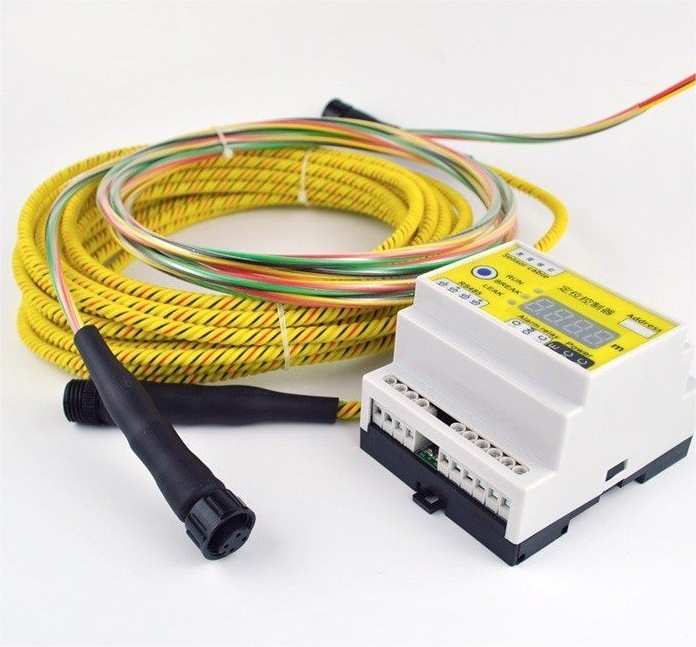
| Locating cable system | Finding a position along a compatible sensing circuit | Does the selected controller provide distance information, not only wet/dry state? |
| Level transmitter | Continuous depth in a sump or tank | Is the task depth monitoring rather than a thin spill on a floor? |
For conductivity-based detection, liquid and contamination affect the electrical response. A water detector is not automatically suitable for oils, nonconductive solvents or every low-conductivity water application. Request an application test with an appropriate representative liquid where suitability is uncertain.
Likewise, a controller's device address identifies an electronic node or zone. It does not prove that the system can report the exact wet position along a cable. Specify zone indication and distance-to-leak functions separately.
A single long zone can reduce controller count while making an alarm harder to investigate. Separate equipment groups or rooms when that distinction helps a technician locate the release. Name zones by physical area and keep a route drawing near the controller or in the maintenance record.
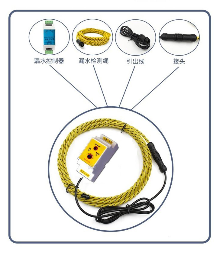
Check compatibility among the controller, sensing cable, connection leads and end termination. Do not join arbitrary cable types simply because the connectors fit. Confirm maximum sensing length, permitted joints, bend restrictions and cleaning method for the selected combination; none should be inferred from the color of the cable or an unlabelled photograph.
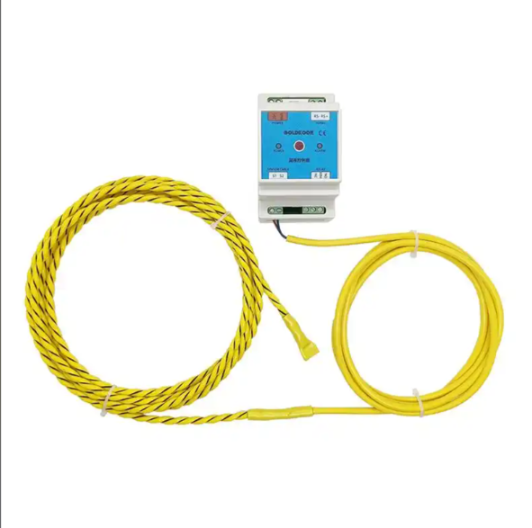
A dry contact, powered switching output and RS485 interface need different receiving arrangements. Confirm terminal function, contact rating or electrical output before connecting a BMS input. If RS485 Modbus RTU is specified, obtain the register map and the meaning of alarm, fault and normal states.
BACnet, Wi-Fi, LoRa, cellular transmission and an API are separate capabilities to verify, not interchangeable names for remote access. A gateway can be part of the design when it supports the required interfaces. An alarm relay alone does not establish direct compatibility with every building-management network.
Ask what happens on loss of controller supply and on a broken or disconnected sensing circuit. If the selected equipment provides separate fault supervision, preserve that distinction at the BMS. If it does not, assess the limitation rather than displaying every absence of a wet alarm as proof of a healthy circuit.
Plan a controlled wet test at an accessible sensing position using the method permitted for the chosen equipment. Protect nearby electrical equipment and avoid introducing water into an unsafe area. Confirm the local indication first, then the receiving BMS or alarm destination. Record which zone responded and whether the displayed label matches the actual location.
Repeat the test at representative parts of a long route where the test method allows it. A test at the controller end alone does not demonstrate every exposed section. Where fault supervision is required and supported, test a controlled circuit disconnection as a different condition from liquid detection.
Afterward, remove the liquid, clean or dry the sensing parts as required and check restoration. Some systems latch an alarm until reset; others restore automatically. Confirm the intended behavior and record any remaining contamination. Resetting the display without restoring the detector can leave the system unable to respond properly to another event.
Water leak detection sensors may feed an alarm or an appropriately engineered shutoff arrangement. Closing a valve can interrupt cooling or another essential service, so a generic wet alarm should not automatically trigger every available valve. The building or process owner needs to define the affected supply, permitted response and restart procedure.
Specify the final action and test it under controlled conditions if automatic control is included. A successful alarm test is not proof that a valve moved, that water flow stopped or that backup cooling remained available. Remote notifications also need a responsible recipient and a response plan.
For enquiries, send NiuBoL a marked floor plan, likely liquid sources, detection route, required zone information and the existing BMS interface. If the actual task is monitoring a sump or storage depth, review a suitable continuous water-level transmitter instead of treating an immersion probe as a floor leak cable.
No. A basic detector may report only its point or zone. Distance-to-leak information requires a compatible locating controller and sensing circuit, and the indicated wet position may differ from the source of the release.
Base length on the mapped water paths and inspection zones, then check the selected controller's permitted circuit arrangement. Room area alone is not an adequate cable-length specification.
Do not assume it. Conductivity-based water detection may not respond as required to oil or other nonconductive liquids. Specify the actual liquid and obtain a suitable detector or representative test.
Check the actual output and receiving input. A compatible relay input or documented protocol arrangement may work, but RS485, Modbus and BACnet should not be treated as identical interfaces.
Test representative wet positions, local and remote indication, required fault states and restoration after cleaning or drying. Test any automatic shutoff separately, with the owner's approved response procedure.
Specify water leak detection sensors around physical water paths and actionable zones. Confirm the exact controller and cable functions, preserve fault information where available, and test both alarm delivery and restoration. This produces a more useful installation than relying on generic cable-length, battery-life or sensitivity promises.
Prev:Water Tank Level Indicators: Depth, Percentage or Usable Volume?
Next:Liquid Level Sensors for Tank Control: Continuous Readings or Switches?
Related recommendations
Sensors & Weather Stations Catalog
 Agriculture Sensors and Weather Stations Catalog-NiuBoL.pdf
Weather Stations Catalog-NiuBoL.pdf
Agriculture Sensors Catalog-NiuBoL.pdf
Water Quality Sensor Catalog-NiuBoL.pdf
Related products
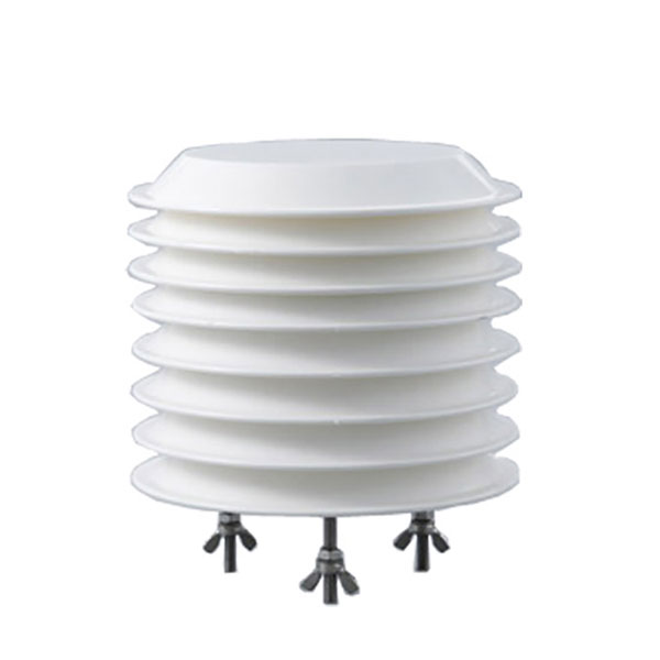 Combined air temperature and relative humidity sensor
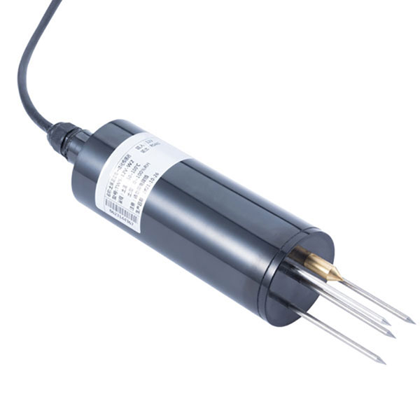 TDR Soil Moisture & Temperature Sensor for irrigation| RS485 |4-20mA| NBL-S-THR
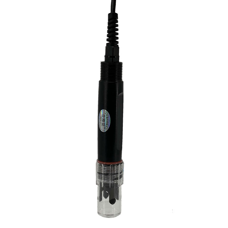 Soil pH sensor RS485 soil Testing instrument soil ph meter for agriculture |NBL-S-PH
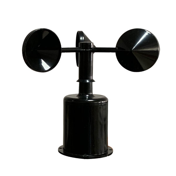 Wind Speed sensor Output Modbus/RS485/Analog/0-5V/4-20mA
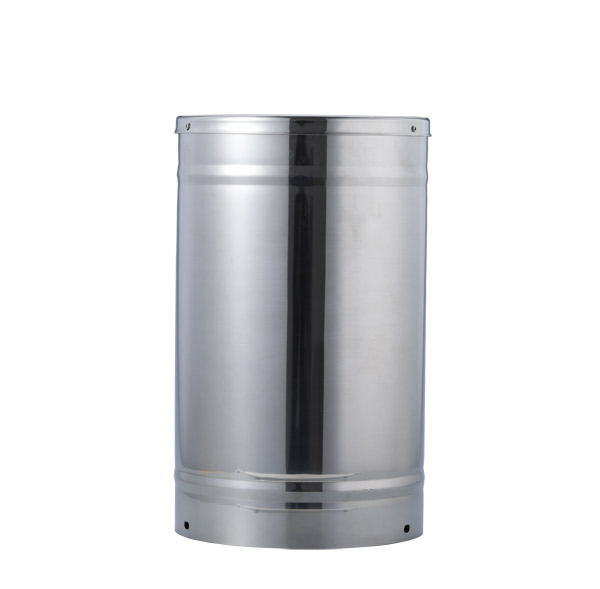 Tipping bucket rain gauge for weather monitoring auto rainfall sensor RS485/Outdoor/stainless steel
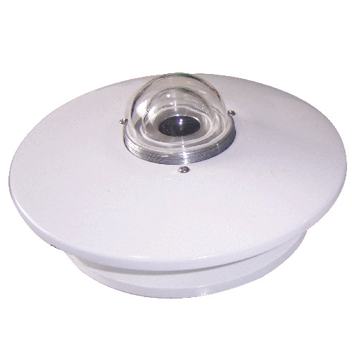 Pyranometer Solar Radiation Sensor 4-20mA/RS485


Screenshot, WhatsApp to identify the QR code
WhatsApp number:+8615367865107
(Click on WhatsApp to copy and add friends)