





— Blogs —
—Products—
 Consumer hotline +8618073152920
WhatsApp:+8615367865107
Address:Room 102, District D, Houhu Industrial Park, Yuelu District, Changsha City, Hunan Province, China
Product knowledge
Time:2025-10-29 15:56:47 Popularity:1320
Water tank level indicators should state whether they display depth, distance, percentage of a configured range or calculated volume. Those values are not interchangeable. For a NiuBoL level-monitoring installation, establish the sensor reference and tank geometry before configuring the local display or remote dashboard. A digital screen does not by itself improve the underlying measurement.
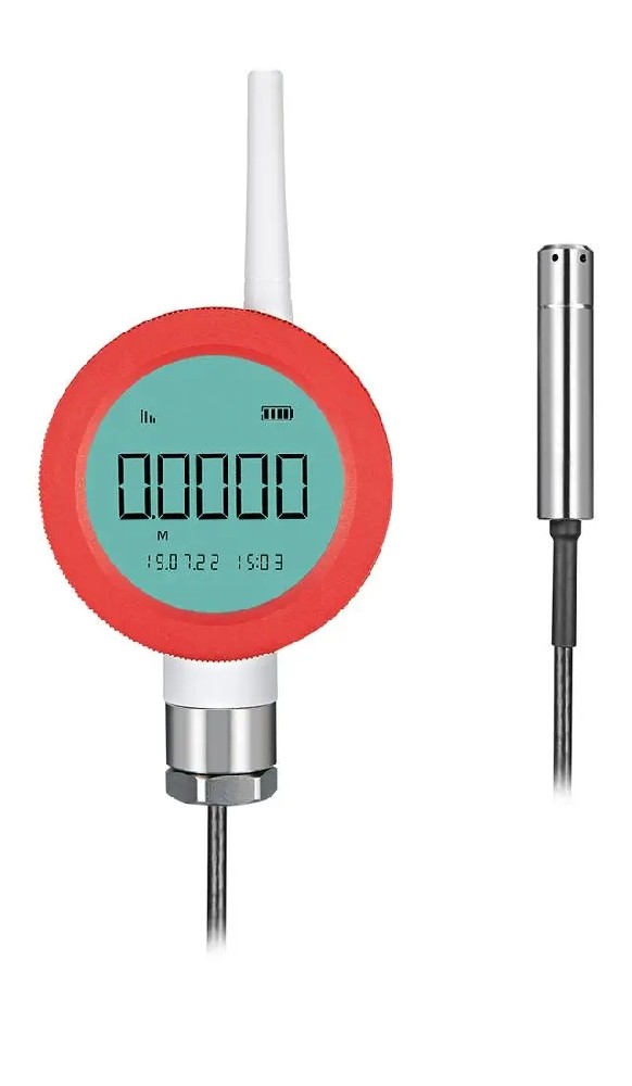
An operator seeing 60% may reasonably assume that 60% of the tank's water remains. The instrument may instead mean 60% of its selected measurement range. That distinction matters when the sensor is above the bottom, the configured range extends beyond the useful tank depth, or the tank has a curved cross-section.
Put the quantity and unit beside the value. Useful labels include water depth above a named datum, distance below the sensor, or calculated stored volume. Avoid an unexplained percentage when different operators use the value for replenishment, stock reporting and pump availability.
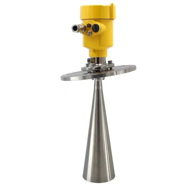
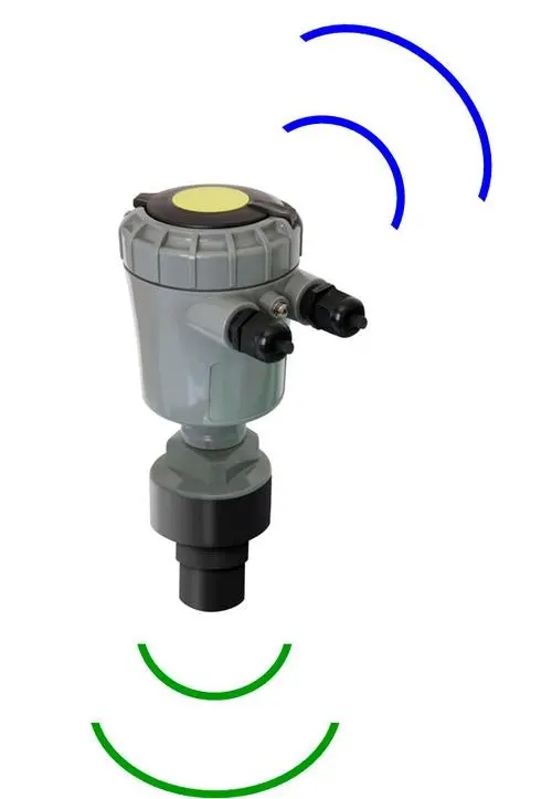
A top-mounted non-contact instrument may report distance to the water surface. As the tank fills, that distance becomes smaller. Level can be calculated as the reference distance to the selected zero datum minus the measured distance, provided both use the same origin and installation geometry.
For an illustrative reference distance of 3.0 m and surface distance of 1.2 m, level above that datum is 1.8 m. This is a calculation example, not the range or accuracy of the pictured instrument. Record the reference after mounting; replacing a bracket or changing the sensor position can require a reference check.
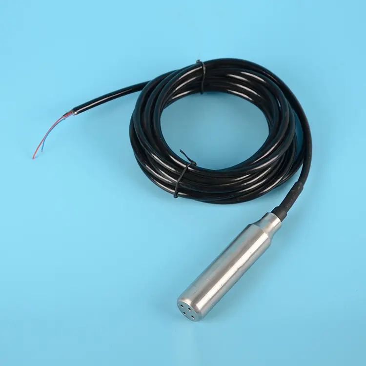
A hydrostatic probe measures the liquid column above its sensing diaphragm. If the diaphragm is 0.2 m above the tank floor, 1.0 m above the diaphragm corresponds to 1.2 m above the floor, under the assumed pressure and density conditions. The sensor's reading should not silently be relabeled as floor-referenced depth.
Document probe position, liquid density assumptions and the selected range. A vented probe's atmospheric reference also needs protection. Water ingress or blockage in the vent path can affect the measurement even while the display continues to update normally.

| Displayed quantity | Required information | Common mistake |
|---|---|---|
| Depth | Defined zero datum and compatible sensor conversion | Ignoring height between the diaphragm and tank floor |
| Distance | Sensor reference point and direction of measurement | Interpreting a smaller distance as a lower level |
| Range percentage | Configured zero and full-scale endpoints | Calling it stored-volume percentage |
| Stored volume | Validated tank geometry or a capacity table | Assuming volume always changes linearly with depth |
| Usable volume | Stored volume and operational limits | Counting water below the usable outlet as available supply |
In a vertical tank with a constant cross-sectional area, volume changes linearly with depth over that constant-area portion. In a horizontal cylindrical or irregular tank, it does not. Use the actual dimensions or an appropriate tank-capacity relationship rather than choosing a linear scaling simply because the display offers one.
For a simple vertical-sided example with area 2 m2, a 1.8 m depth represents 3.6 m3. If the minimum usable depth is 0.3 m, water above that boundary is 3.0 m3. These examples illustrate the distinction; real operating reserves and intake conditions must be defined for the installation.
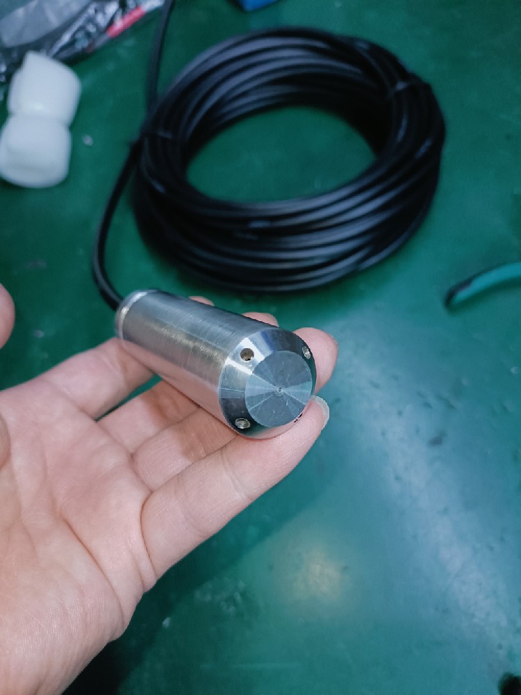
The NBL-L-WLPS submersible water-level transmitter provides RS485 Modbus RTU data. Its supply is DC 10-30 V, maximum power is 0.2 W and default baud rate is 4800 bps. Range is selected for the application rather than fixed by the tank's name or the display size.
Read the configured engineering unit and decimal arrangement before applying display scaling. A value expressed in millimeters should not be decoded as meters. Keep the sensor's original measurement distinguishable from the receiving system's calculated percentage or volume so commissioning can identify where a discrepancy originates.

Water tank level indicators at the tank, control room and remote office should use a consistent reference. If one screen shows depth and another shows volume, label that difference. Also display observation age or availability; the last received value is not necessarily the present water condition.
A remote connection requires compatible acquisition and communications equipment. RS485 does not itself include cellular transmission, an API or a cloud service. Check those functions separately without replacing a reliable local indication unnecessarily. A readable local gauge can remain useful during a remote-network interruption.
Compare the sensor reading, local display and remote value at an accessible known level using a safe reference method. Check more than one position where practical. A single matched point cannot reveal every scaling or geometry error. Keep any software offset associated with its physical reason rather than repeatedly adjusting it to conceal a moving probe.
Level indication is also separate from pump control and overfill protection. Define operating actions and independent safeguards where required; do not assume that adding a remote percentage display prevents overflow or dry running.
Only when the value is explicitly configured as volume percentage using the correct tank relationship. A percentage of depth or sensor range may represent a different volume fraction.
Check their reference points and quantities first. One may report depth above its diaphragm while the other reports distance below its antenna. Convert them to a shared datum before comparing measurements.
A depth measurement needs an appropriate level-to-volume relationship to become liters. Confirm whether the transmitter or receiving software performs that calculation and which geometry it uses.
Not inherently. Measurement accuracy belongs to the complete sensing and conversion arrangement. More digits or remote access do not correct an unsuitable reference or tank-volume calculation.
Provide tank dimensions or a capacity table, liquid and temperature, reference positions, desired units and the receiving equipment. Tell NiuBoL whether the task is local depth indication, remote inventory or a separate control function.
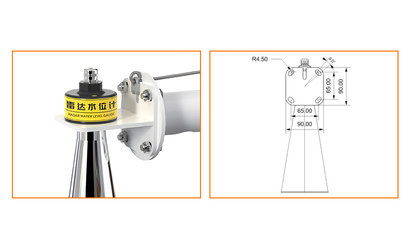
Specify water tank level indicators by the meaning of the displayed value. Define the datum, distinguish depth from volume and usable storage, and check every receiving screen against that definition. Correct conversion is more useful than a larger display or an unsupported promise of automatic water savings.
Prev:Evolution of Agrometeorological Stations: Records, Loggers and Networks
Next:Water Leak Detection Sensors: Cable Zones, Placement and Alarm Tests
Related recommendations
Sensors & Weather Stations Catalog
 Agriculture Sensors and Weather Stations Catalog-NiuBoL.pdf
Weather Stations Catalog-NiuBoL.pdf
Agriculture Sensors Catalog-NiuBoL.pdf
Water Quality Sensor Catalog-NiuBoL.pdf
Related products
 Combined air temperature and relative humidity sensor
 TDR Soil Moisture & Temperature Sensor for irrigation| RS485 |4-20mA| NBL-S-THR
 Soil pH sensor RS485 soil Testing instrument soil ph meter for agriculture |NBL-S-PH
 Wind Speed sensor Output Modbus/RS485/Analog/0-5V/4-20mA
 Tipping bucket rain gauge for weather monitoring auto rainfall sensor RS485/Outdoor/stainless steel
 Pyranometer Solar Radiation Sensor 4-20mA/RS485


Screenshot, WhatsApp to identify the QR code
WhatsApp number:+8615367865107
(Click on WhatsApp to copy and add friends)

