





— Blogs —
—Products—
 Consumer hotline +8618073152920
WhatsApp:+8615367865107
Address:Room 102, District D, Houhu Industrial Park, Yuelu District, Changsha City, Hunan Province, China
Product knowledge
Time:2025-01-17 16:15:10 Popularity:1916
A visibility measuring instrument replacement must match the required measurement, mounting, power and data interface, not just the existing cable label. The NiuBoL NBL-W-VS measures meteorological optical range from 5 m to 10 km using forward scattering. It is not a 100 km visibility instrument, a particulate mass sensor or a complete runway visual range system.
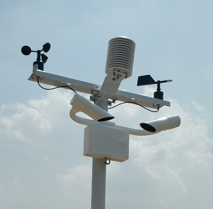
A replacement enquiry often begins with a failed sensor and a photograph of its terminals. That identifies only part of the task. The receiving PLC, RTU or station logger may expect a particular distance unit, range, message format and fault indication. A physically similar replacement can therefore produce a plausible but incorrect display.
Record the old instrument's model, measured quantity, electrical supply, mounting arrangement and communication document. Export a short record from the receiving system if possible. Then identify what must remain compatible and what the contractor can reconfigure. Do not assume that an RS485 instrument can replace another without changes to the driver.
| Replacement check | Question to resolve | Consequence if missed |
|---|---|---|
| Measured quantity | Is the requirement MOR, another visibility definition or an operational aviation system? | Different quantities may be incorrectly treated as interchangeable |
| Range and units | What distances must be reported, and in metres or kilometres? | The screen may scale values incorrectly or expect an unavailable range |
| Interface | Which protocol, registers and validity states does the receiver use? | A successful electrical connection may still deliver unusable information |
| Mechanical fit | Can the support carry and orient the selected instrument correctly? | Mounting may obstruct the optical sample or prevent servicing |
The NBL-W-VS visibility sensor uses DC 12 V and RS485 Modbus RTU. Its standard cable length is 10 m. Check the field route, connector arrangement and wiring identification before deciding to reuse the old cable. The same wire color or connector shape does not establish the same pin assignment.
Check voltage at the instrument under operating load, rather than only at the cabinet supply. Include the logger and modem in the station power assessment; the sensor's approximately 0.8 W average consumption does not describe the complete installation. Any existing protection and grounding arrangement also needs to remain suitable after the replacement.
| Parameter | NBL-W-VS specification | Replacement implication |
|---|---|---|
| Measurement | Meteorological optical range, 5 m-10 km | Do not configure the receiver as a 100 km measurement channel |
| Accuracy | 2% at up to 2 km; +/-10% from 2-10 km | Assess the required operating range and verification conditions |
| Supply and average power | DC 12 V; approximately 0.8 W | Check the installed power circuit and complete station load |
| Communication | RS485 Modbus RTU; default 9600 bps; function 03; minimum communication interval 1000 ms | Implement the selected model's register definitions |
| Environment | -40 to 80 C; 0-95% RH; IP65 | Check exposure, connections and enclosure requirements |
| Optical geometry | Forward-scattering angle 39-51 degrees | Use the model's geometry rather than a universal diagram angle |
| Standard cable | 10 m | Assess extensions and termination before ordering |
Forward-scattering instruments estimate MOR from a local optical sampling volume. They do not measure visibility along every line of sight in the monitored area. A new device can therefore differ from an old one because of exposure as well as instrumental response. Preserve the monitoring purpose when deciding where the replacement belongs.
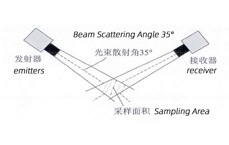
The emitter and receiver are arranged so their optical paths intersect in a sampling region. Generic diagrams show that principle, but their labeled angles are not specifications for every visibility instrument. For NBL-W-VS, use the 39-51 degree specification and the corresponding mechanical installation information.
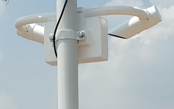
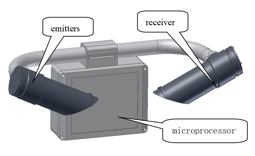
Do not alter the emitter-receiver geometry to imitate an older instrument or a sketch. Mount the instrument as a complete assembly, horizontally with the open sloping ends facing downward. Keep the optical region clear of signs, branches and other obstructions, and avoid direct sunlight entering the receiver.
If the old location was beside exhaust, irrigation spray or a persistent local plume, simply reusing the pole may preserve a siting problem. Assess whether that local atmosphere represents the required road section or site. A convenient power connection does not make an observation representative.
Read the new instrument locally before connecting its value to an existing alarm or display. Verify address, serial settings, register interpretation and units. A decoded 1000 m value must appear as 1 km if the display uses kilometres. Do not assume a successful Modbus reply proves that the correct register has been read.
Check how the system shows an unavailable instrument, an out-of-range condition and a loss of communication. An old last-good value should not continue to look current. If software uses replacement-device values in an alarm rule, the operator should review the rule against the new range and data behavior before returning it to service.
A side-by-side observation can help identify gross disagreement, but the old sensor is not automatically a reference standard. A clear-day comparison or an improvised obstruction test does not establish accuracy over the full MOR range. Where calibration evidence is required, agree the test method and documentation separately.
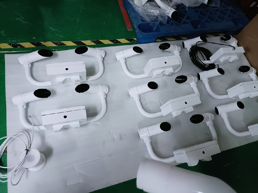
Send the existing model and wiring document, required MOR range, power arrangement, receiver model and protocol details. Include photographs and dimensions of the support and the route to the cabinet. State whether firmware or platform changes are permitted, and whether an outage window is required for commissioning.
NiuBoL can then review the NBL-W-VS configuration and the integration work separately. A replacement offer should identify sensor supply, mounting changes, cable work, driver configuration and verification. Wireless reporting requires suitable external communication equipment; it is not a built-in function of the RS485 optical instrument.
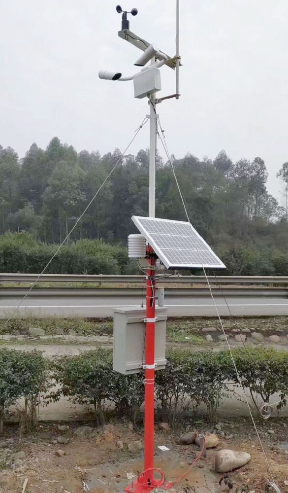
Not as a like-for-like range replacement. NBL-W-VS measures 5 m-10 km. Check whether that range meets the actual project requirement before considering changes to the receiving system.
No. Confirm Modbus RTU settings, registers, scaling, status information and wiring. The receiver may need a different driver or configuration even when both instruments use RS485.
Only after checking structural suitability, clamp fit, optical clearance, orientation and service access. Also review the site's exposure; replacing the instrument will not correct an unrepresentative location.
Do not specify automatic calibration without configuration-specific evidence. Inspection and optical cleaning are different from calibration, and project verification should use an agreed method.
MOR and RVR are different requirements. A project requiring operational RVR equipment needs a separate assessment; a general atmospheric visibility sensor should not be quoted as equivalent.
A visibility measuring instrument replacement succeeds when the measurement and the receiving system remain compatible. Match the NBL-W-VS range, power, mounting and Modbus data deliberately, then verify the displayed quantity before operational use. Treat wireless reporting, calibration evidence and any aviation requirements as separate project responsibilities.
Prev:Intelligent Construction Site Dust Monitoring System
Next:Rainfall Monitoring Equipment: Empowering Water Resource Management
Related recommendations
Sensors & Weather Stations Catalog
 Agriculture Sensors and Weather Stations Catalog-NiuBoL.pdf
Weather Stations Catalog-NiuBoL.pdf
Agriculture Sensors Catalog-NiuBoL.pdf
Water Quality Sensor Catalog-NiuBoL.pdf
Related products
 Combined air temperature and relative humidity sensor
 TDR Soil Moisture & Temperature Sensor for irrigation| RS485 |4-20mA| NBL-S-THR
 Soil pH sensor RS485 soil Testing instrument soil ph meter for agriculture |NBL-S-PH
 Wind Speed sensor Output Modbus/RS485/Analog/0-5V/4-20mA
 Tipping bucket rain gauge for weather monitoring auto rainfall sensor RS485/Outdoor/stainless steel
 Pyranometer Solar Radiation Sensor 4-20mA/RS485


Screenshot, WhatsApp to identify the QR code
WhatsApp number:+8615367865107
(Click on WhatsApp to copy and add friends)

