





— Blogs —
—Products—
 Consumer hotline +8618073152920
WhatsApp:+8615367865107
Address:Room 102, District D, Houhu Industrial Park, Yuelu District, Changsha City, Hunan Province, China
Product knowledge
Time:2023-08-17 10:38:26 Popularity:1938
Quick Answer: Wind direction sensor applications include weather records, agricultural operations, pollutant-dispersion studies and industrial wind monitoring. The useful output is the direction the wind comes from, referenced consistently to the site. Choose the sensor and acquisition method around low-wind response, exposure and data processing; a correctly wired instrument can still produce a misleading record if its orientation or averaging is wrong.
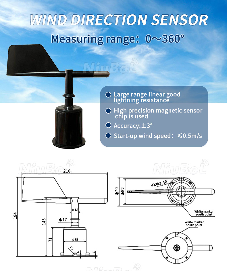
A vane measures its angular position relative to the installed housing. Turning that into an operational decision requires context: wind speed, sensor location, time and the convention used by the receiving system. A displayed value of 270 degrees is not sufficient to identify a safe work condition, explain a concentration event or describe a whole site's airflow.
| Application | Why direction matters | Additional measurements |
|---|---|---|
| Weather stations | Local wind climatology and event records | Wind speed, temperature, pressure and rainfall |
| Agriculture | Spray planning, ventilation and field exposure | Wind speed, humidity and temperature |
| Air-quality monitoring | Relating concentration changes to source direction | Wind speed and pollutant instruments |
| Wind energy | Resource and turbine-operation analysis | Calibrated wind speed and site metadata |
A wind rose combines the frequency of direction sectors with wind-speed classes. Define the averaging interval and the rule for calm or invalid records before comparing stations. A direction-only channel cannot distinguish a frequently recorded sector during light, variable airflow from the sector associated with stronger winds.
For a spray-area observation or greenhouse outdoor reference, place the measurement where it represents the activity rather than a sheltered yard. Wind direction should be read with speed and the relevant temperature and humidity data. It is one input to an operational assessment, not a universal permission to spray or a substitute for the equipment and product requirements applicable to the work.
Synchronise concentration and wind records before investigating whether elevated readings occur with wind from a particular sector. Review low-wind periods, obstructions and possible travel time between a source and the measurement point. A matching direction supports investigation; it does not by itself establish which source caused a concentration increase.
Use direction to examine exposure, recurring approach sectors and local airflow around fixed equipment. Wind-energy assessment or a regulated safety system may require a specified measurement method, calibration evidence and additional instruments. A general-purpose vane is not automatically qualified for turbine control, aviation reporting or a protective interlock simply because it reports degrees.
The NiuBoL NBL-W-DS wind direction sensor is available with RS485 Modbus RTU, 4-20 mA or 0-5 V output according to the ordered version. These are alternatives, not a promise that one unit supplies every signal simultaneously. Specify the supply voltage and output together with the PLC, RTU or data logger input.
For a 4-20 mA version scaled across 0-360 degrees, the conversion is direction = 360 x (current in mA - 4) / 16. Thus 8 mA represents 90 degrees and 12 mA represents 180 degrees. For a 0-5 V version, direction = 360 x voltage / 5, so 1.25 V represents 90 degrees. These are scale checks, not a mechanical calibration of the vane.
Check the analogue input's common reference, load and range. An input configured for 0-20 mA will not use the same engineering scale as a 4-20 mA input. On RS485, match the device address, communications settings and register interpretation to the ordered firmware. Do not infer degrees, sector codes or decimal scaling from the connector alone.

The National Weather Service definition of wind direction uses the direction from which the wind blows. A wind from the west is therefore a westerly wind, even though the air is travelling east. Verify that a platform arrow and a numeric heading use the same convention; some graphics indicate the travel direction.
For the NBL-W-DS, the white south-reference mark on the housing must face geographic south. Do not assume every vane uses a north-facing installation mark. Establish the site reference with a suitable survey or orientation method, then secure the bracket and confirm the reported headings before leaving the mast.
Nearby roofs, trees and towers distort airflow. Mount the sensor at the required height and document boom orientation and local declination practice. The system must convert the sensor's electrical zero into a geographic direction consistently.
Where a compass is used, account for local magnetic declination and avoid taking the bearing against a steel mast or energised equipment. A constant angular offset across several reference positions points toward an orientation or software-offset issue. A direction that changes erratically only in one sector is more likely to require an exposure or mechanical-clearance check.
| NBL-W-DS characteristic | Selection significance |
|---|---|
| Range: 0-360 degrees | Normalise equivalent north endpoints consistently in the logger and reports. |
| Specified accuracy: +/-3 degrees | Mounting-reference error is additional; electrical resolution alone does not establish site accuracy. |
| Starting wind speed: no more than 0.5 m/s | Do not assume useful direction at every near-calm condition. |
| Supply: 5 V or 12-24 VDC version | Order the variant matching the station supply and selected output. |
| Power consumption: approximately 0.15 W | Include logger, communications and any separately specified heating in the station budget. |
| Operating temperature: -40 to 80 degrees C | This range does not establish operation with ice on the vane. |
| Standard cable: 2.5 m; other lengths by configuration | Check extension, receiving input and mechanical support before installation. |
| Enclosure requirement for new orders: IP65 | Specify IP65 for the ordered assembly and protect cable entries; this is not an immersion or direct-lightning rating. |
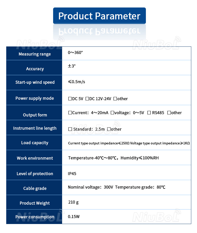
Protection ratings vary by version. The earlier-version parameter illustration includes IP45; specify IP65 for the outdoor assembly being ordered rather than assuming that an older unit has the same enclosure construction. Match the confirmed supply, output and connector arrangement to the actual unit.
Direction is circular data: 359 degrees and 1 degree are close, not far apart. Software should use vector methods when calculating averages. Calm periods may have an undefined or unstable direction and should be handled according to the reporting method rather than forced into an invalid average.
For wind roses, store direction and speed with matching timestamps and documented averaging intervals. Air-quality projects should also align pollutant data to the same time basis before interpreting source direction.
For example, the arithmetic average of 359 and 1 degrees is 180 degrees, which is physically misleading. For equally weighted directional observations, average their sine and cosine components and recover the angle with a two-argument arctangent, then normalise it to 0-360 degrees. The result for this pair is north, not south.
Distinguish that circular mean from a speed-weighted mean wind vector. The latter uses wind-speed components and answers a different question when speeds vary. With equal, opposite observations the mean vector can approach zero, making its direction unstable or undefined. Record the chosen method and avoid forcing such a result into a confident compass heading.
Keep calm, variable and missing-data flags separate from valid north. The display may use zero or 360 for north, while a formal reporting code may reserve a value for calm. Apply the convention required by the reporting scheme; do not overwrite a valid sensor angle or treat a communications failure as calm weather.
| Observed behaviour | First useful check |
|---|---|
| A similar offset at several headings | Check the housing reference, configured offset and whether the display uses from- or toward-direction. |
| A jump between values near 0 and 360 | Inspect endpoint normalisation and circular averaging before treating it as a mechanical fault. |
| Direction remains unchanged as airflow changes | Confirm a fresh timestamp, then inspect free vane movement, cable condition and actual signal change. |
| Unstable direction during very light wind | Check wind speed and the calm rule; the vane may not have sufficient aerodynamic force. |
| Consistent abnormalities from one approach sector | Inspect obstructions and mast or boom effects in that sector. |
Cold sites may require a heated version and a larger power budget. Coastal or industrial sites need suitable materials and connector protection. Inspect the vane, bearings, fasteners and cable, and compare direction against a physical reference after service.
For a quotation, describe the application, exposure, required output, supply and logger model. Include cable length, mounting interface, enclosure requirement, icing conditions and any calibration evidence needed. If both speed and direction are required, identify whether separate sensors or an integrated wind instrument fit the installation; compare their actual configurations rather than the number of parameters in a headline.
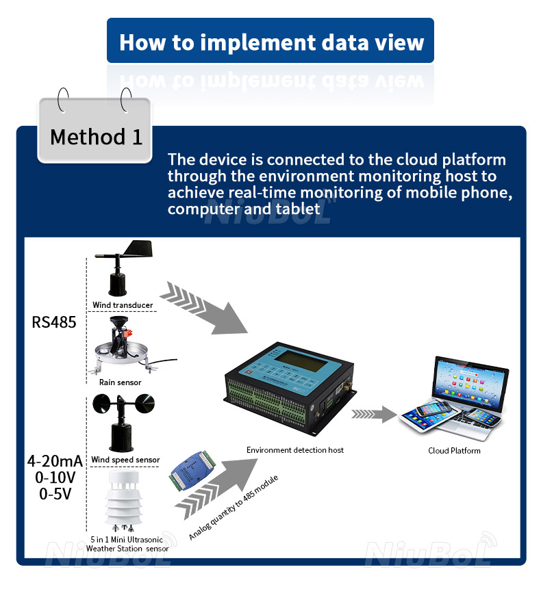
The sensor provides a local measurement. A compatible data logger or gateway supplies remote transmission, with the sampling and averaging required by the application. Verify direction and speed together at the logger and platform so a correct field reading is not lost through a different timestamp or reporting convention.
It can report an angle, but speed is needed to interpret calm periods and many operational or dispersion questions. Specify both channels when producing wind roses or investigating events that depend on airflow strength.
Check whether the display shows where air is travelling while the sensor reports where it comes from. Also check whether the mounting reference was reversed. Compare several physical headings before applying a software correction.
No. Its white reference mark identifies south and should face geographic south. Use the orientation method appropriate to the installation and verify the output at known directions after securing the bracket.
No. The software must handle circular data, and a speed-weighted vector requires simultaneous speed readings. An arithmetic average can turn near-north observations into a false southerly result. Define the averaging method and the calm or variable-wind rules.
No. IP65 concerns enclosure ingress protection. Ice can still restrict vane motion, and site lightning protection requires its own design. Specify IP65 for the ordered wind-sensor assembly and separately address icing, grounding and surge protection where required.
Use the input the PLC actually supports: current input for 4-20 mA, voltage input for 0-5 V, or a suitable serial interface and driver for RS485 Modbus RTU. Confirm supply, scale and wiring for that version; a spare digital input is not an analogue measurement channel.
Compare the same output, supply, accuracy, starting threshold, enclosure, cable and mounting scope. Add heating only if it is specifically offered and required. Check calibration, installation support and receiving-system work separately so a sensor-only price is not confused with an installed monitoring point.
Wind direction sensor applications are distinguished by the decision made from the angle. Match the NiuBoL wind sensor and output to the measurement task, establish its geographic reference and process direction as circular data. These checks make the record interpretable without attributing site errors or software behaviour to the sensor alone.
Related recommendations
Sensors & Weather Stations Catalog
 Agriculture Sensors and Weather Stations Catalog-NiuBoL.pdf
Weather Stations Catalog-NiuBoL.pdf
Agriculture Sensors Catalog-NiuBoL.pdf
Water Quality Sensor Catalog-NiuBoL.pdf
Related products
 Combined air temperature and relative humidity sensor
 TDR Soil Moisture & Temperature Sensor for irrigation| RS485 |4-20mA| NBL-S-THR
 Soil pH sensor RS485 soil Testing instrument soil ph meter for agriculture |NBL-S-PH
 Wind Speed sensor Output Modbus/RS485/Analog/0-5V/4-20mA
 Tipping bucket rain gauge for weather monitoring auto rainfall sensor RS485/Outdoor/stainless steel
 Pyranometer Solar Radiation Sensor 4-20mA/RS485


Screenshot, WhatsApp to identify the QR code
WhatsApp number:+8615367865107
(Click on WhatsApp to copy and add friends)

