





— Blogs —
—Products—
 Consumer hotline +8618073152920
WhatsApp:+8615367865107
Address:Room 102, District D, Houhu Industrial Park, Yuelu District, Changsha City, Hunan Province, China
Product knowledge
Time:2023-08-18 09:43:23 Popularity:1923
Quick Answer: Wind speed sensor applications should be specified by the required observation, site exposure and receiving system, not by country or a single maximum range. Choose the measurement method and actual model, then verify mounting, scale and averaging. Operational alarms also require an appropriate controller and response procedure beyond the wind sensor itself.
| Application | Measurement purpose | Site issue |
|---|---|---|
| Automatic weather station | Routine wind records | Mounting height and obstacle exposure must be documented. |
| Agriculture | Spray limits, ventilation and lodging-risk context | Canopy and structures can create local turbulence. |
| Industrial site | Operational alarms and dispersion context | Alarm thresholds and response responsibility must be approved. |
| Solar or wind project | Environmental and performance records | Use project standards for location, height and data quality. |
A cup anemometer converts rotor speed into wind speed. It is widely understood, easy to inspect visually and often suitable for routine automatic weather stations. Moving parts introduce starting friction and wear, so low-wind response and bearing condition deserve attention. A propeller sensor is directional and is commonly paired with a vane or aligned to a flow path. Its use depends on whether the project needs horizontal wind from any direction or a known duct or tunnel direction.
An ultrasonic wind sensor calculates wind speed from acoustic transit time between transducers. It has no rotating bearings and can report speed and direction from one body. Performance still depends on geometry, signal processing, precipitation, icing and contamination. Heated versions require additional power. The comparison should use the specified uncertainty, starting or threshold behaviour, update rate and environmental conditions of the exact models under consideration.
For gust monitoring, confirm whether the output is an instantaneous value, short average or maximum over a defined interval. A weather archive may use a different averaging method from a crane, bridge or industrial alarm system. The logger and platform must preserve the calculation method; otherwise two displays labelled "wind speed" can report different results from the same air flow.
A sensor supporting environmental trend review is not automatically suitable for a protective machine-control function. For a crane, tracker, bridge or other consequential operating decision, use the equipment and project's required measurement and control arrangements. Do not infer approval from a general wind-range specification.
| NBL-W-SS characteristic | Configuration value | Selection consequence |
|---|---|---|
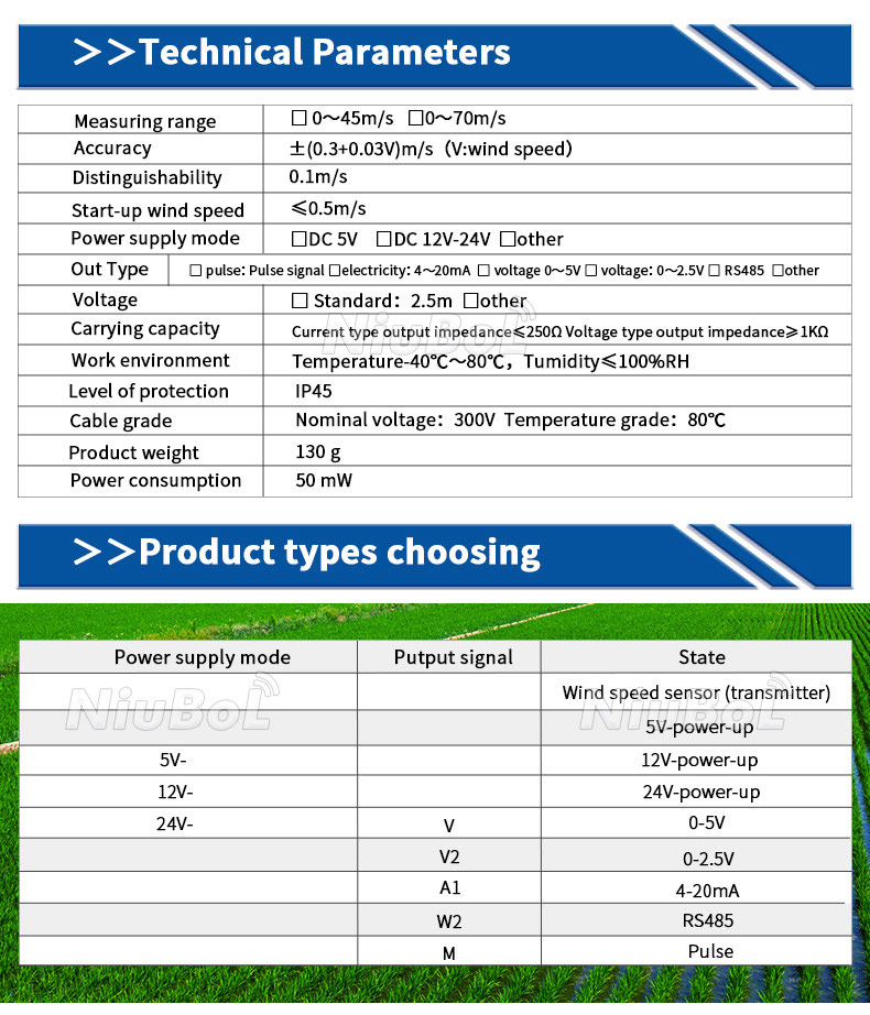
| Measuring range | 0-45 m/s or 0-70 m/s option | Use the actual ordered full scale in the acquisition. |
| Accuracy | +/-(0.3 + 0.03u) m/s, where u is wind speed in m/s | The percentage term depends on wind speed; it is not simply +/-0.3 m/s everywhere. |
| Resolution and starting threshold | 0.1 m/s resolution; starting speed no more than 0.5 m/s | A fine display step does not remove mechanical starting behavior. |
| Supply versions | 5 V DC or 12-24 V DC option | Check the supplied version rather than assuming a common input for all outputs. |
| Output versions | Pulse, 4-20 mA, 0-5 V, 0-2.5 V or RS485 by order | Confirm the actual signal and compatible receiving input. |
| Operating conditions | -40 to +80 degrees C; humidity up to 100% RH | Assess icing, contamination and the complete station separately. |
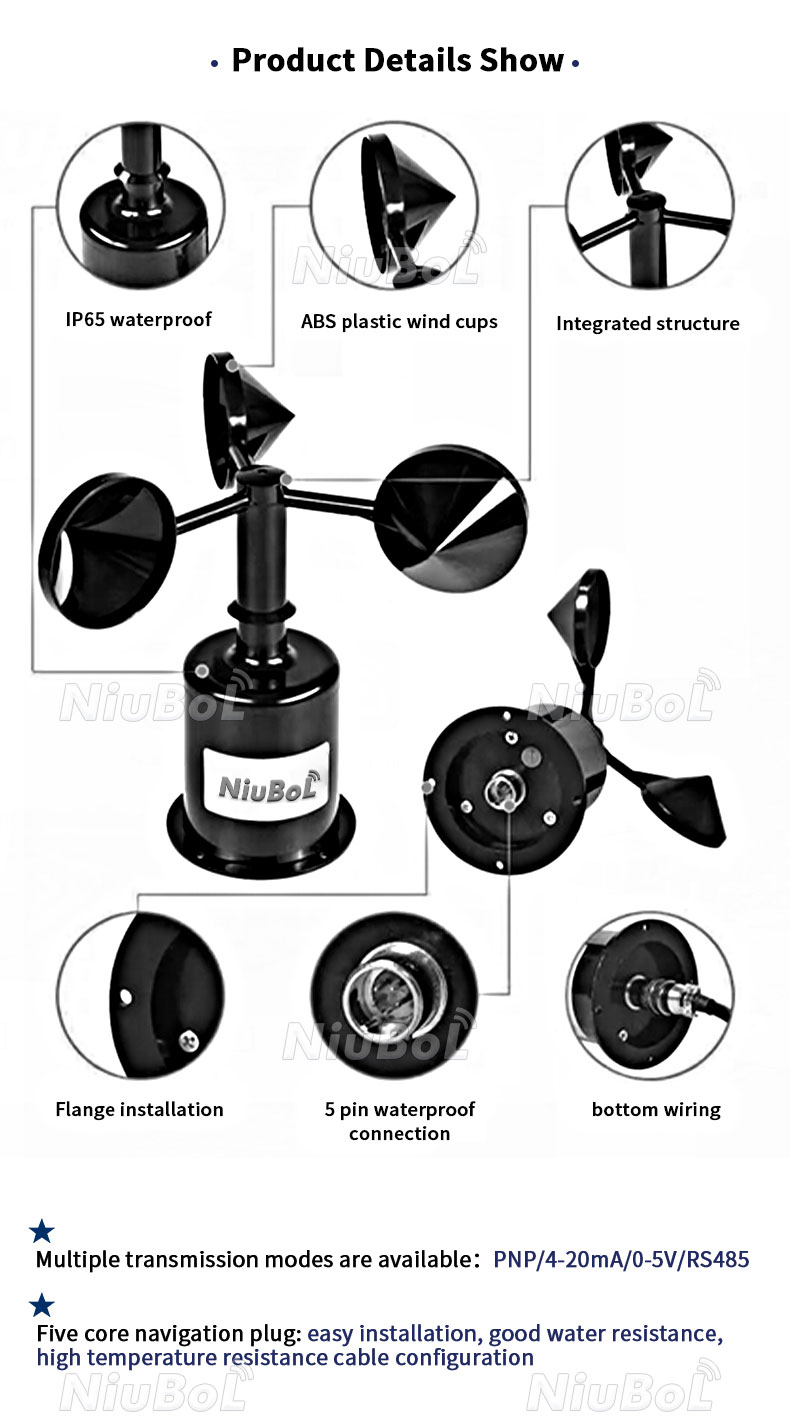
| Protection and power | IP65; stated product consumption 50 mW | Protect connectors and include acquisition and other loads separately. |
| Cable | Standard 2.5 m; rated voltage 300 V and temperature rating 80 degrees C | Specify jacket and extension arrangement; cable rating is not sensor supply voltage. |
For the stated accuracy expression, a wind speed of 20 m/s gives a numerical term of +/-(0.3 + 0.03 x 20) = +/-0.9 m/s. This explains the specification; it does not establish the uncertainty of an obstructed or poorly mounted field point.
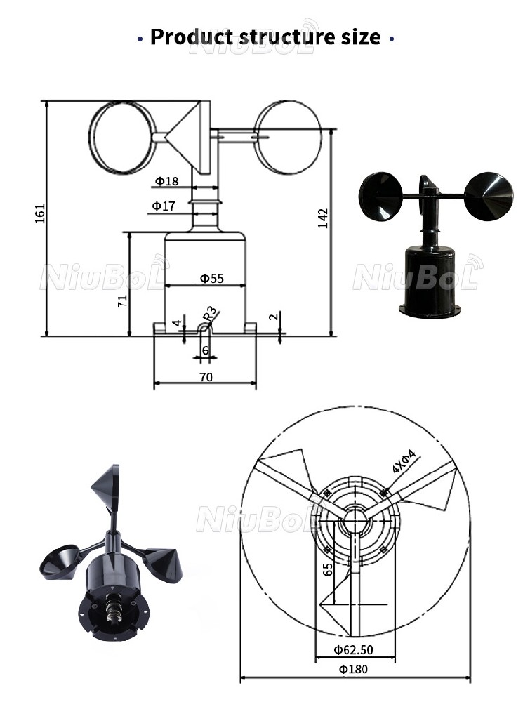
Specify IP65 for the supplied NBL-W-SS configuration and confirm the delivered identification against the order. A generic product illustration is not the acceptance record for the ordered range, output or protection. Keep those values with the instrument identity rather than taking a rating from an older illustration.
Buildings, trees, parapets and even the supporting mast alter local flow. A sensor placed behind an obstacle can show a repeatable but unrepresentative value. The installation method should define height, horizontal clearance, boom direction and the intended measurement area. In a plantation or greenhouse project, canopy growth changes exposure over time. In an industrial project, new structures and exhaust outlets can do the same.
Terrain also matters. Ridge, valley and coastal sites can have strong local differences. One sensor may be enough for a compact, uniform decision area, but it cannot describe every point across complex terrain. When several stations are used, apply the same orientation, averaging and maintenance method so their records remain comparable.
| Project need | Required output | Configuration note |
|---|---|---|
| Ventilation trend | Wind speed; direction when openings are orientation-dependent | Keep the sensor clear of the greenhouse structure |
| Spray operation | Speed and direction | Use approved operating limits and a representative location |
| Industrial alarm | Speed, averaging or gust value, alarm status | Define hysteresis, delay and safe response |
| Meteorological archive | Speed, direction and documented averaging | Follow the project observation method |
For a 4-20 mA version, the full scale matters to conversion. At an illustrative 8 mA, a 0-45 m/s scale gives 11.25 m/s, while a 0-70 m/s scale gives 17.5 m/s. These are electrical scaling examples, not a reason to change the scale of an actual delivered unit.
If the local display and receiving logger disagree, compare the signal version, selected full scale, units and processing interval before adjusting the instrument. For a pulse version, obtain the actual frequency relationship; for a digital version, use its delivered data definition. Do not apply one version's conversion to another output.
Low-wind behavior also needs interpretation. A stopped or slowly moving cup under very light airflow is different from a power or data fault. A valid calm condition should remain distinct from a missing observation in the logger and platform.
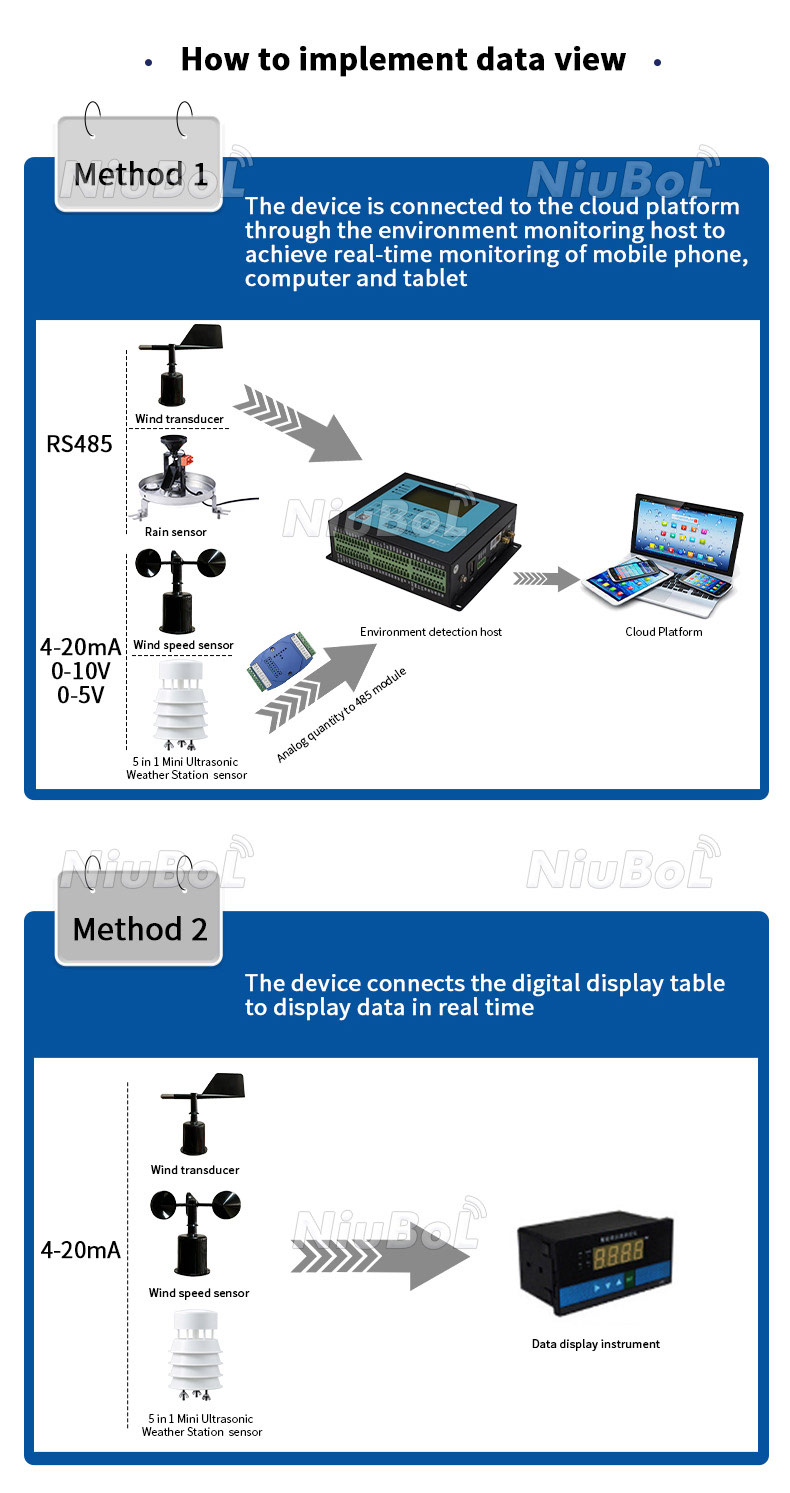
An RS485 network should use a planned daisy-chain topology, suitable twisted-pair cable and unique device addresses. Long branches and star connections can create reflections and intermittent communication. Termination and biasing depend on the complete bus design; they should not be added independently at every sensor. Power-voltage drop must be calculated separately from communication distance, especially when several instruments share one cable and the supply is located at ground level.
Outdoor wind sensors are exposed above surrounding structures, so grounding, shielding and surge protection need coordination with the mast and station design. Surge devices reduce risk but do not make a poor lightning-protection layout safe. The procurement scope should identify who provides the mast, cable, junction box, earth system, surge devices and commissioning.
An RS485 Modbus RTU instrument needs the actual address, serial settings, register data type, scale and units checked with the receiving PLC, RTU or logger. A common connector does not establish identical mapping across models. Field communication also remains separate from the gateway's remote network connection.
A functional input simulation can verify scaling and downstream alarm behavior. It does not calibrate aerodynamic response. Similarly, manually moving a rotor can check a limited response but cannot establish a traceable wind-speed calibration or acceptance under every field condition.
For a project alarm, test the defined statistic, threshold, timing and controller response through an approved procedure. A short maximum and a longer average are different signals. Local protective functions, where required, should not depend solely on an unverified remote notification.
A wind speed sensor can pass an electrical test and still produce poor project data. Typical causes include mounting within the wake of a pole or roof, incorrect north alignment, mixed units, an undocumented averaging interval and a logger that interprets a signed or multi-register value incorrectly. Ice or contamination can stop a mechanical rotor, while deposits or precipitation can affect an ultrasonic acoustic path. Trend review and physical inspection are both required.
Replacement also needs control. Installing a different sensor model without updating scaling, register maps or metadata can introduce a step change that looks like a weather trend. Record the old and new model, serial number, mounting height, orientation, date and configuration. If data continuity matters, run an overlap comparison where the project method permits it.
For alarm applications, test the complete chain rather than only spinning the sensor. Apply a controlled input or approved simulation, verify the logger value, cross the threshold, check delay and hysteresis, confirm local output and remote notification, then record the result. This separates measurement acceptance from alarm-system acceptance.
Documentation should state the reporting convention for calm conditions, missing direction and values outside the approved range. The platform should not silently replace an invalid value with zero because zero wind is a valid measurement. Keep raw status or quality information where the sensor and logger support it, and show technicians the last valid timestamp during fault diagnosis.
Provide NiuBoL the observation purpose, speed-only or combined speed/direction requirement, expected conditions, output and receiving input. Include mounting height and location, cable distance, power and exposure to icing, salt, dust or vibration. State any required calibration, replacement or control-interface conditions.
Compare the sensor, mount, cable, acquisition and installation work on the same basis. A low body price may exclude an input converter or serviceable mount, while a complete station offer may include functions already available on site. Choose the actual configuration instead of ranking unlike packages by one figure.
Only when its exposure represents the intended decision area. Terrain and structures can create substantial local differences, so additional points may be needed for distinct operating locations.
No. Starting behavior, useful uncertainty and the selected method matter separately. Review them at the operating conditions that the project actually needs to observe.
No. Its stated expression includes a wind-speed-dependent term: +/-(0.3 + 0.03u) m/s. At 20 m/s, that numerical term is +/-0.9 m/s before installed exposure is considered.
Specify IP65 for the supplied NBL-W-SS configuration and verify the delivered identification. Field terminations and acquisition enclosures need their own suitable protection.
No. Cable, topology, baud rate, grounding, surge protection and power drop must be assessed for the complete installation. Test at the intended final arrangement rather than relying on a universal distance claim.
No. It verifies the receiving signal path and scaling. Sensor calibration and installed exposure are separate questions requiring appropriate methods.
The range, conversion, averaging, location or instrument response may have changed. Retain the old and new identities and configuration, and compare overlapping observations where the project method permits.
Wind sensor selection depends on application and exposure as well as the ordered model. Use the correct range, accuracy expression, IP65 requirement and output definition, then verify acquisition and any alarm separately. A connected value is useful only when its location and processing preserve the intended wind observation.
Prev:Wind Speed Sensor Price: Cost Factors and RFQ Checklist
Next:Wind speed sensor is a widely used sensor and its application
Related recommendations
Sensors & Weather Stations Catalog
 Agriculture Sensors and Weather Stations Catalog-NiuBoL.pdf
Weather Stations Catalog-NiuBoL.pdf
Agriculture Sensors Catalog-NiuBoL.pdf
Water Quality Sensor Catalog-NiuBoL.pdf
Related products
 Combined air temperature and relative humidity sensor
 TDR Soil Moisture & Temperature Sensor for irrigation| RS485 |4-20mA| NBL-S-THR
 Soil pH sensor RS485 soil Testing instrument soil ph meter for agriculture |NBL-S-PH
 Wind Speed sensor Output Modbus/RS485/Analog/0-5V/4-20mA
 Tipping bucket rain gauge for weather monitoring auto rainfall sensor RS485/Outdoor/stainless steel
 Pyranometer Solar Radiation Sensor 4-20mA/RS485


Screenshot, WhatsApp to identify the QR code
WhatsApp number:+8615367865107
(Click on WhatsApp to copy and add friends)

