





— Blogs —
—Products—
 Consumer hotline +8618073152920
WhatsApp:+8615367865107
Address:Room 102, District D, Houhu Industrial Park, Yuelu District, Changsha City, Hunan Province, China
Product knowledge
Time:2026-09-12 09:00:00 Popularity:190
Automatic field weather station maintenance is easier to price and perform when the station has a documented baseline. Without the original sensor orientation, mast height, cable route, logger settings and power budget, a service visit can restore a live dashboard without restoring comparable data. This guide is for owners and contractors planning unattended agricultural, environmental or energy-site stations across seasons.
Record the location, mast and sensor heights, north reference, nearby obstructions, model and serial numbers, firmware or logger configuration, channel units, sampling and upload intervals, battery and solar-panel details, and photographs of every exposed connector. Save the initial 24-hour data trace and the first reference checks. Those records let maintenance distinguish a changed sensor from a changed site: a new building, taller crop or shifted panel can change the measured wind or radiation without any electrical fault.
Assign responsibility by subsystem. The instrument supplier can provide model-specific cleaning and replacement guidance, while the installer may own mast, grounding and cable work and the system integrator may own clock synchronization, storage and alarms. A single annual visit that checks only the probe face will not find a failing battery or a logger that has been storing the wrong units for months.
Begin with an on-site safety check: lightning risk, mast stability, safe access and any lockout required for power work. From the ground, check tilt, loose supports, vegetation and new obstructions. At the sensor, inspect drainage paths, housings, seals, UV-damaged cable, strain relief and insect or bird contamination. Do not dismantle a sealed ultrasonic head merely to clean it; follow the selected model's service instructions and use a soft, non-damaging method on exposed sensing surfaces.
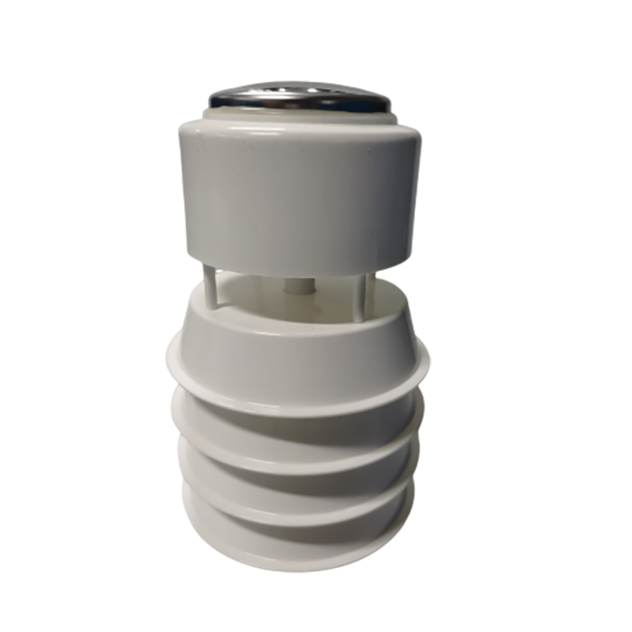
The photographed NBL-W-61MUWS six-element head combines ultrasonic wind, temperature, humidity, pressure and piezoelectric rainfall. Its lack of moving wind cups does not remove the need to inspect the north bearing, acoustic paths and the rain-impact surface. A separate tipping-bucket rain gauge, if supplied in another station package, has its own funnel, level and bucket-cleaning requirements; never apply one rain sensor's service test to another principle.
| Maintenance trigger | Check in the field | Decision before closing the visit |
|---|---|---|
| Wind direction shifts after mast work | Compare the sensor's north mark and recorded bearing. | Correct the physical reference; preserve old and new settings in the log. |
| Rain record stays at zero during known rain | Inspect the actual rain-sensing surface and logger channel; use the model's functional test. | Separate sensor fault from dry site conditions or data-mapping error. |
| Overnight data gaps | Read battery voltage under load, modem events and logger restarts. | Fix the power or telemetry path before blaming a sensor. |
| All channels step at the same instant | Check supply, clock, register map and recent configuration changes. | Do not recalibrate unrelated sensing elements together. |
| One channel drifts while others remain plausible | Check exposure, contamination and a suitable reference. | Clean, verify or replace that channel using its own method. |
Measure supply voltage at the head during its operating state, not only at the battery with the cable disconnected. Inspect solar-panel shading and connectors, charge-controller events, battery condition and whether the logger's storage survives a power interruption. If winter autonomy is marginal, compare the actual worst-season energy available with the station's load: sensor, logger, modem, heater if fitted, and upload schedule. Do not size a battery from the sensor's nominal power alone.
For RS485 Modbus RTU channels, check address uniqueness, baud rate, parity, register mapping, scaling and units at both the sensor and logger. A cable shield or surge protector altered during repair can create intermittent failures. Confirm the logger clock, time zone and record interval against a known reference; a correct wind value attached to the wrong hour can corrupt a seasonal analysis. Test both local storage and the remote platform, including behavior when the network is unavailable and later returns.
The NBL-W-61MUWS product information lists 12-24 VDC, RS485 with Modbus communication, 9600 baud, approximately 0.3 W average consumption, IP65 and a 2.5 m standard cable. These values are for that head only. They are a useful check against the delivered tag and power budget, not a specification for the entire weather station, cabinet, modem or later sensors.
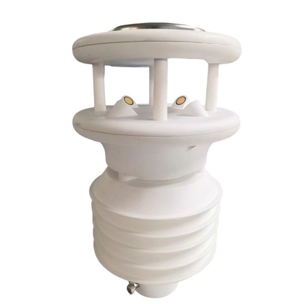
The NBL-W-10GUWS pictured here adds environmental channels to a wind-and-weather head. Its product page specifies 9-24 VDC, RS485 Modbus, IP65 and different average power figures with or without the dust channel. It also offers solar radiation or illuminance as an either/or option. A maintenance plan must list the actual delivered channels; otherwise a technician may look for a missing parameter that was never ordered.
Dust inlets need inspection for blockage and contamination; an external radiation sensor needs a clean, correctly oriented optical surface. A piezoelectric rain surface and a tipping bucket respond differently to a field test. Do not pour water onto an integrated head or replace parts without the delivered procedure. If the operator needs calibrated rainfall totals for a formal network, specify the required reference method and check whether the selected rain principle meets it.
Flat wind speed in a windy period might reflect a blocked acoustic path, incorrect register, frozen upload or an exposed head in the wake of a new structure. First compare the local instrument and logger values, then examine power and communications. A direction offset that appeared after maintenance is more likely a bearing or configuration change than a failed transducer. Keep the as-found settings before altering them.
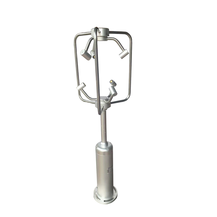
The NBL-W-3D-UWDS in the fourth photograph measures three wind components for sites that require vertical as well as horizontal flow information. Its published interface is RS485 Modbus, with 9-24 VDC supply and IP66 protection. It is not a drop-in replacement for a two-dimensional head unless the logger map, mounting and required data fields are revised. A spare-parts list should identify the exact model and connector rather than saying only "ultrasonic wind sensor."
No single visit interval suits a clean research field, a dusty roadside and a salt-exposed coastal site. Start with the supplier's model-specific instructions and a conservative initial inspection plan; tighten the interval after faults, storms, dust events or evidence of fouling. Record as-found and as-left observations, not only "cleaned." This distinction shows whether a recurring problem requires a design change such as better access, cable protection or a different mounting position.
Replace consumables and suspect parts based on observed condition and documented performance. Keep compatible spares for critical stations: the exact sensor variant, connector, surge component, fuse, modem and battery type where those items are serviceable. Before ordering, compare the serial number, output and firmware or register map with the installed unit. A visually similar replacement can shift parameter offsets in the data platform.
For a distributed network, group visits by route but keep site-specific inspection sheets. Seasonal photographs are particularly useful where crops or trees alter exposure. If a station is moved, document the old and new coordinates and heights and mark the time-series break; do not silently join the two records as though the measurement environment were unchanged.
After physical work, compare each active channel with a reasonable local reference or functional check. Verify that the head's values reach the logger and remote display with the expected units and timestamp. Force or simulate a communication fault where permitted and confirm the alarm shows invalid data rather than holding a credible-looking last value. Review the next upload cycle and a complete record interval before declaring the visit closed.
A maintenance contract should state whether it includes mast access, sensor cleaning, instrument verification, consumables, battery replacement, cellular service, data review, travel and emergency callouts. Quote those tasks separately enough that a distributor or project owner can compare coverage. NiuBoL can identify model-specific spares and documentation when given the installed station list and the site's operating conditions.

Q1. Does an ultrasonic wind sensor need no maintenance?
A1. It avoids cup-and-vane bearing wear, but still needs checks of the north reference, exposure, acoustic paths, mounting, cable and data mapping. Do not open a sealed head unless its service instructions require it.
Q2. How often should a field station be inspected?
A2. Set an initial schedule from the delivered manuals and site exposure, then adjust after observing fouling, storms, battery performance and data gaps. A fixed interval copied from another site is not evidence of adequacy.
Q3. What should be checked when rainfall stays at zero?
A3. Confirm actual rain at the site, the rain-sensor principle, its surface or funnel condition, channel mapping and logger receipt. Use the specified functional test for that model rather than a generic water-pour test.
Q4. Can a 3D ultrasonic anemometer replace an integrated weather head?
A4. Not as a direct like-for-like change. The 3D model provides wind vectors, while an integrated head may also provide temperature, humidity, pressure and rainfall. Reconcile missing channels, wiring and register maps first.
Q5. Why is the battery healthy at noon but data disappears overnight?
A5. Daytime panel input can mask inadequate battery capacity, a weak cell or excessive modem duty. Measure voltage under overnight load and inspect the charge and restart logs before changing sensor calibration.
Q6. What must a replacement order specify?
A6. Include model, serial or configuration, output, connector, cable length, active channels and receiving logger. Match the delivered register map before dispatching a visually similar head.
Q7. What evidence closes a maintenance ticket?
A7. Keep as-found and as-left photos, readings, configuration changes, parts used, reference checks, an end-to-end upload and a tested fault state. Note any data interval that should be flagged or excluded.
Automatic field weather station maintenance should protect the continuity and meaning of the record, not merely keep hardware powered. Preserve the commissioning baseline, inspect exposure and power as well as sensors, and close every service visit with an end-to-end data check. Specify exact NiuBoL models and service scope so replacement and quotation decisions remain technically comparable.
Prev:Automatic Water Surface Evaporation Station Installation Guide
Next:Automatic Soil Moisture Monitoring System Installation and Maintenance
Related recommendations
Sensors & Weather Stations Catalog
 Agriculture Sensors and Weather Stations Catalog-NiuBoL.pdf
Weather Stations Catalog-NiuBoL.pdf
Agriculture Sensors Catalog-NiuBoL.pdf
Water Quality Sensor Catalog-NiuBoL.pdf
Related products
Combined air temperature and relative humidity sensor TDR Soil Moisture & Temperature Sensor for irrigation| RS485 |4-20mA| NBL-S-THR
 Soil pH sensor RS485 soil Testing instrument soil ph meter for agriculture |NBL-S-PH
 Wind Speed sensor Output Modbus/RS485/Analog/0-5V/4-20mA
 Tipping bucket rain gauge for weather monitoring auto rainfall sensor RS485/Outdoor/stainless steel
 Pyranometer Solar Radiation Sensor 4-20mA/RS485


Screenshot, WhatsApp to identify the QR code
WhatsApp number:+8615367865107
(Click on WhatsApp to copy and add friends)

