





— Blogs —
—Products—
 Consumer hotline +8618073152920
WhatsApp:+8615367865107
Address:Room 102, District D, Houhu Industrial Park, Yuelu District, Changsha City, Hunan Province, China
Product knowledge
Time:2026-06-06 09:36:47 Popularity:1075
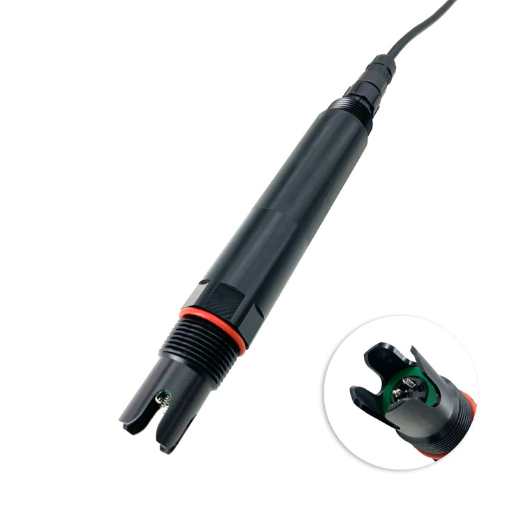
Quick Answer: An electrode residual chlorine sensor is suitable for continuous disinfection monitoring only when its chlorine measurement basis, sample conditions and controller interpretation match the process. For the NiuBoL NBL-WQ-CL configuration discussed here, the measurement is specified as HClO, with a 0-2.000 mg/L range and a circulation flow cell. It should not be treated as an unrestricted total-chlorine analyser or installed directly in a pressurised main without sample conditioning.
A tender that asks for residual chlorine in mg/L is incomplete if it does not identify the chlorine quantity and reporting basis. Free chlorine and total chlorine are different measurements. Free chlorine includes hypochlorous acid, HClO, and hypochlorite, OCl-. Total chlorine additionally includes combined forms such as chloramines. Chloride ions are not residual disinfectant chlorine, and an ORP reading is not a chlorine concentration.
The NBL-WQ-CL uses constant-voltage chlorine measurement and identifies its range as HClO. Do not relabel that channel as total chlorine. Before using it to meet a free-chlorine requirement, establish how the configured instrument's output relates to the required free-chlorine quantity over the site's pH and temperature conditions. A label change in the PLC cannot resolve a difference between measurands.
Temperature compensation and pH tolerance also mean different things. Automatic Pt1000 compensation does not establish automatic pH correction. The permitted medium range of pH 4-9 describes an operating condition; it does not prove an unchanged response to total free chlorine throughout that range. This distinction matters when the process pH changes after chemical dosing or varies between operating modes.
The sensor measures a conditioned sample, while the controller decides what to do with the measurement. A typical installation takes water from a representative process point, controls the flow through a circulation cell, reads the sensor into a PLC or data logger and records the value with its acquisition time and status. Sample take-off, drain arrangements and access for a reference measurement are part of the measurement channel.
The sampling point must answer the operator's question. A point immediately after chemical injection can show mixing effects rather than the residual at the intended control location. A remote network point may reveal downstream residual changes but introduces transport and communication delays. Choose the point with the process designer; do not assume the sensor itself establishes the required disinfectant contact time or verifies microbiological performance.
| Parameter | Configuration value | Selection consequence |
|---|---|---|
| Principle and quantity | Constant-voltage electrode measurement; HClO | Agree on the required chlorine species and reporting basis before comparing results. |
| Range and resolution | 0-2.000 mg/L HClO; 0.001 mg/L resolution | The display increment is not the measurement uncertainty. |
| Chlorine accuracy | +/-5% or +/-0.05 mg/L | Define the applicable percentage basis and acceptance tolerance for the ordered configuration. |
| Temperature measurement | +/-0.5 degrees C; automatic Pt1000 compensation | Do not interpret temperature compensation as pH compensation. |
| Sample conditions | 5-50 degrees C; pH 4-9; working pressure below 0.1 MPa | Provide a suitable sample route if the main process is outside these conditions. |
| Flow-cell operation | Circulation cell; recommended sample flow 30-60 L/h | Maintain steady flow over the sensing region and provide a visible way to check it. |
| Power and output | 12-24 VDC +/-10%; 0.2 W at 12 V; RS485, Modbus RTU | Budget the complete sampling and control system separately from the sensor load. |
| Body and ingress protection | POM and PTFE components; 30 x 233 mm sensor; IP68 | Ingress protection does not increase the permitted sample pressure. |
| Cable installation | 6 mm cable outer diameter; waterproof treatment required at cable joints | Specify ordered length and jacket compatibility for the site rather than inferring them from IP68. |
| Calibration | Zero and slope adjustment | Use competent personnel and a reference matched to the chlorine quantity. |
These limits describe the named configuration. A higher-range electrode or a different flow assembly needs its own specifications. In particular, a pressure limit from another chlorine product should not be carried across to this installation. Specify the sensor, flow cell and sample fittings together, including the pressure that can occur if a downstream valve closes.
A residual chlorine flow cell needs a dependable water supply, not simply a connection that occasionally fills with water. Position the electrode so that the sensing region receives the intended inlet flow. Keep the flow within 30-60 L/h and avoid conditions that introduce bubbles, stagnant pockets or uncontrolled pressure. A flow indicator and accessible isolation points make a low-reading investigation much more direct.
Consider transport delay before setting an alarm expectation. In an illustrative calculation, a sample line containing 1 L of water at 30 L/h has a nominal volume-to-flow residence time of two minutes. This excludes mixing, dispersion, electrode response and controller filtering. A short sensor response specification cannot remove the time taken for a changed process sample to reach the electrode.
Sample conditioning can also change the sample. A long warm line, prolonged residence or deposits may alter the chlorine residual before measurement. Keep the route practical to inspect, minimise unnecessary hold-up and take reference samples close to the flow-cell measurement point. Do not solve a poor sample route by applying a calibration offset that hides the difference from the process.
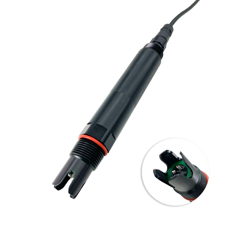
A new electrode, or one returning after extended storage, needs activation before it is judged in service. Plan for a 24-hour tap-water activation period for this configuration, followed by stable operation in the sample cell. Activation is not a substitute for checking the sensor against the site's reference method. Avoid promising immediate closed-loop readiness on the day an unconditioned electrode is connected.
For a reference comparison, identify whether the method measures free or total chlorine, its usable range and the reporting units. If a DPD test is used, distinguish the free-chlorine procedure from the total-chlorine procedure. Test a representative sample promptly under that method's conditions and record sample temperature, pH and flow. Comparing different chlorine quantities, or samples taken at different times and locations, can create an apparent sensor error.
Perform zero adjustment in chlorine-free water only after the reading is stable. Slope adjustment requires an appropriate known HClO concentration and controlled flow-cell conditions; the relevant calibration range is 1-2 mg/L for this configuration. Chlorine reference preparation and verification require trained personnel. Do not use an unverified stock dilution as though its calculated concentration were an independently established reference value.
The standard serial format for this configuration is 9600 baud, eight data bits, no parity and one stop bit. Assign a unique device address and check the actual device settings before adding it to an existing bus. The specified wiring is red for positive supply, black for GND, blue for RS485 A, white for RS485 B and the bare conductor for shielding. Do not transfer wire colours from a different water-quality model.
The measurement reply contains four 16-bit words: chlorine value, its decimal-place count, temperature value and its decimal-place count. For example, an integer chlorine value of 359 with three decimal places represents 0.359 mg/L. This is not a pair of floating-point values. Check the sensor reply and the PLC display together at more than one concentration so that a scale error is not mistaken for a calibration error.
Keep calibration writes separate from routine reads. Use the exact register mapping for the delivered firmware and restrict write access to authorised maintenance functions. A Modbus reply proves communication, not sample flow or electrode health. Log communication timeouts and the age of the last valid observation; do not allow a stale number to appear as a fresh chlorine result.
A drinking water disinfection monitoring point can support residual trending and a designed dosing loop after commissioning. It does not independently prove pathogen removal or replace the plant's disinfection operating procedure. The controller needs its own output limits, operating permissions and defined behaviour when sample flow is lost or the measurement becomes invalid. Those responses depend on the plant design, not on a universal sensor default.
For cooling water chlorine monitoring, identify the disinfectant chemistry and whether operation is continuous or intermittent. Do not assume an HClO electrode will measure chlorine dioxide, bromine or every mixed oxidant correctly. Compare the sample conditions and potential interferences with the proposed electrode before relying on the trend to terminate a dosing event.
Pool and recirculating-water installations need the same separation between measurement and control. A pH channel can help interpret changes in disinfectant chemistry, but it must be an actual additional measurement. An ORP channel can provide a different process indication; it cannot be substituted for a concentration result or used to claim that the chlorine electrode has been independently verified.
Investigate in a practical order: confirm a fresh, valid digital value; check flow and pressure at the cell; inspect for bubbles and deposits; then compare a nearby sample using the chosen reference method. If both measurements are low, investigate the process and sample route. If they disagree, first check chlorine quantity, units, pH conditions and sampling time before changing the electrode slope.
After cleaning or adjustment, restore stable flow and repeat the comparison before returning to automatic operation. Record the reference result and the change made, so that the next service visit can distinguish progressive electrode drift from repeated hydraulic interruptions. For an enquiry, send the required chlorine quantity, normal and maximum concentration, pH, temperature, available sample pressure and controller details to NiuBoL. Include the proposed flow-cell arrangement and service access.
The configuration described here is specified for HClO, not total chlorine. A requirement including combined chlorine needs a suitable measurement method. Confirm the quantity and reporting basis before specifying the instrument or naming the PLC tag.
This configuration uses a circulation flow cell with pressure below 0.1 MPa and sample flow of 30-60 L/h. A higher-pressure main requires an appropriately designed sample connection and pressure control. IP68 does not permit operation above the working-pressure limit.
Check whether both measure the same chlorine quantity, then compare sampling location, timing, pH and temperature. Verify the handheld test procedure and flow through the electrode cell. Agreement should be assessed using a defined tolerance, not obtained by repeatedly offsetting one instrument to match the other.
No. Resolution is the reported increment. Accuracy, reference uncertainty, sample stability and the applicable chlorine quantity determine a defensible acceptance tolerance. Agree on those conditions before the site test.
Specify the electrode configuration, flow cell, sample fittings, flow indication, cable length, power supply and PLC interface. Identify whether the package includes a controller, installation and commissioning. An electrode-only price is not a complete sampling-channel price.
No. First complete electrode activation, sample-flow checks, scale verification and reference comparison. The plant must also test its response to invalid or stale data and loss of sample flow before enabling the designed automatic dosing function.
Sample deposits, flow stability, reference-check results and electrode condition determine the service interval. Establish an initial inspection plan and adjust it from operating records. A fixed calendar interval cannot guarantee performance in every drinking-water, pool or cooling-water sample.
An electrode residual chlorine sensor becomes useful when the chlorine quantity, conditioned sample and digital interpretation agree. For this NBL-WQ-CL configuration, use the HClO measurement basis, controlled flow cell and stated operating limits, then verify the result against an appropriate reference. Only after those checks should the channel become an input to the plant's designed dosing control.
Prev:Dissolved Oxygen in Aquaculture Management: From Alarm to Recovery
Next:Online Total Hardness Sensor: Softener Outlet and Bypass Selection
Related recommendations
Sensors & Weather Stations Catalog
 Agriculture Sensors and Weather Stations Catalog-NiuBoL.pdf
Weather Stations Catalog-NiuBoL.pdf
Agriculture Sensors Catalog-NiuBoL.pdf
Water Quality Sensor Catalog-NiuBoL.pdf
Related products
 Combined air temperature and relative humidity sensor
 TDR Soil Moisture & Temperature Sensor for irrigation| RS485 |4-20mA| NBL-S-THR
 Soil pH sensor RS485 soil Testing instrument soil ph meter for agriculture |NBL-S-PH
 Wind Speed sensor Output Modbus/RS485/Analog/0-5V/4-20mA
 Tipping bucket rain gauge for weather monitoring auto rainfall sensor RS485/Outdoor/stainless steel
 Pyranometer Solar Radiation Sensor 4-20mA/RS485


Screenshot, WhatsApp to identify the QR code
WhatsApp number:+8615367865107
(Click on WhatsApp to copy and add friends)

