





— Blogs —
—Products—
 Consumer hotline +8618073152920
WhatsApp:+8615367865107
Address:Room 102, District D, Houhu Industrial Park, Yuelu District, Changsha City, Hunan Province, China
Product knowledge
Time:2026-11-09 09:09:24 Popularity:5
A level transmitter powers up, the logger keeps showing 0.75 m, and the tank is empty: RS485 A and B are reversed, so no frame is decoded and the logger holds its last valid value with a fresh timestamp. Field sensor deployment is the work of getting one instrument from unboxing to a trustworthy first reading through wiring, power, addressing, scaling and a fault tree.
In field sensor deployment the soil salinity and EC sensor covers 0–15 mS/cm at 0.01 mS/cm resolution and 0–8000 mg/L at 1 mg/L resolution. Those increments describe the last digit the register can show, not the error of the reading, and confusing the two is the most common way a plausible wrong number gets accepted.
Accuracy is a separate specification with its own convention. The NBL-L-WLPS level transmitter is quoted at Accuracy Class 0.5, a full-scale class rather than a 0.5 mm statement, so the class applies to the whole selected range and not to one reading near zero. Ask whether a quoted error is of reading or of span, and confirm it on the current datasheet. Range, resolution and accuracy are three different numbers; keep them on three separate lines of the acceptance record for this point.
If the job needs to resolve a 0.05 mS/cm change, 0.01 mS/cm resolution is necessary but not sufficient; the accuracy budget must also be smaller than 0.05 mS/cm. Confirm the accuracy figure on the current datasheet before anyone treats the last displayed digit as a tolerance.
The first defensible number on the logger is 7.50 mS/cm. Here is the audit trail that produces it, written backwards from the displayed value, because a field sensor deployment is accepted on the trace and not on the screen, and the arithmetic has to survive a second engineer recomputing it by hand.
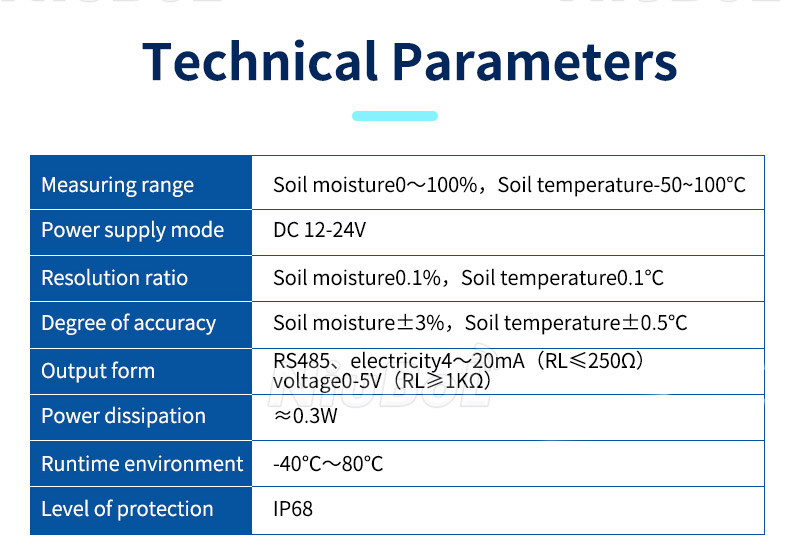
Figure 1. NBL-S-THR TDR soil moisture temperature sensor specifications with RS485 4-20mA and 0-5V output.
Input: raw EC holding register R = 750, EC range 0–15 mS/cm, resolution 0.01 mS/cm, register span 0–1500 counts. Formula: EC = R × 0.01 = 750 × 0.01 = 7.50 mS/cm, cross-checked by ratio as (R / 1500) × 15 = (750 / 1500) × 15 = 7.50 mS/cm. Result: 7.50 mS/cm, matching the logger display before the point is accepted.
Boundary: R must stay within 0–1500; a value outside, a 0xFFFF sentinel, or a no-response timeout is a fault, not a reading. The 0.01 mS/cm figure is resolution and cannot bound the error of that 7.50 mS/cm result. This is an illustrative calculation based on assumed site values, not a measured field record.
Register addresses, count ranges and scaling are typical engineering reference values and assumed site values; check against the current datasheet / nameplate for your instrument before treating the map as fixed, quoting it in a specification, or handing it to a second installer who will wire a different sensor model.
Wiring faults outnumber sensing faults at first power-up in any field sensor deployment. Work the terminals in this order and write down each result, since the 0.75 m reading in the opening case was a held value from a broken bus, not a measurement that scaling could correct.
Measure DC 10–30 V at the sensor end of the cable, not at the panel; 24 VDC is the typical supply for the NBL-L-WLPS. A long run can drop below the minimum while the panel still reads 24 VDC.
Match RS485 A and B to the master. Two cable-color configurations exist: Version A uses Red / Blue for power and Yellow / White for A / B; Version B uses Brown / Black for power and Yellow / Blue for A / B.
Fit 120 Ω termination at both bus ends on a long run and add repeaters when the run requires them.
Assign a unique Modbus address; two devices sharing one address both answer and the master sees CRC errors or timeouts.
Set the baud rate with the whole bus. The default is 4800 bps; the configurable range is 1200–115200 bps.
The receiving end must expose the raw register, not only the scaled engineering value, and it must show its hold-last-value behaviour in the log. That is where the raw word lands before any scaling, and where a 0xFFFF sentinel is first seen.
Scaling is a per-channel contract, and it changes when the selected full measuring range changes. Write down the register, the raw range, the formula and the unit before the first reading is trusted; a correct formula applied to the wrong channel still produces a plausible wrong number that no one will question later.
The analog paths are linear: L = (V / 5) × M for 0–5 V, and L = (I − 4) × M / 16 for 4–20 mA. Both hold only while V stays in 0–5 V or I in 4–20 mA; a signal at 0 V or 3 mA usually means a broken wire, not a zero measurement. Confirm M on the nameplate.
Wrong: a 4–20 mA point hides identity and status in one current. Right: an RS485 Modbus RTU point carries the raw value, the device address and a status word, so a fault can be named and logged instead of guessed at.
In field sensor deployment, mounting geometry can dominate the error budget. If a submerged level transmitter sits 50 mm above the intended datum, every reading carries a +50 mm offset; on the 1000 mm selected range used in the scaling table above, that is a 5% full-scale bias, far larger than the sensor resolution. Check the selected range against the current datasheet / nameplate for your instrument.
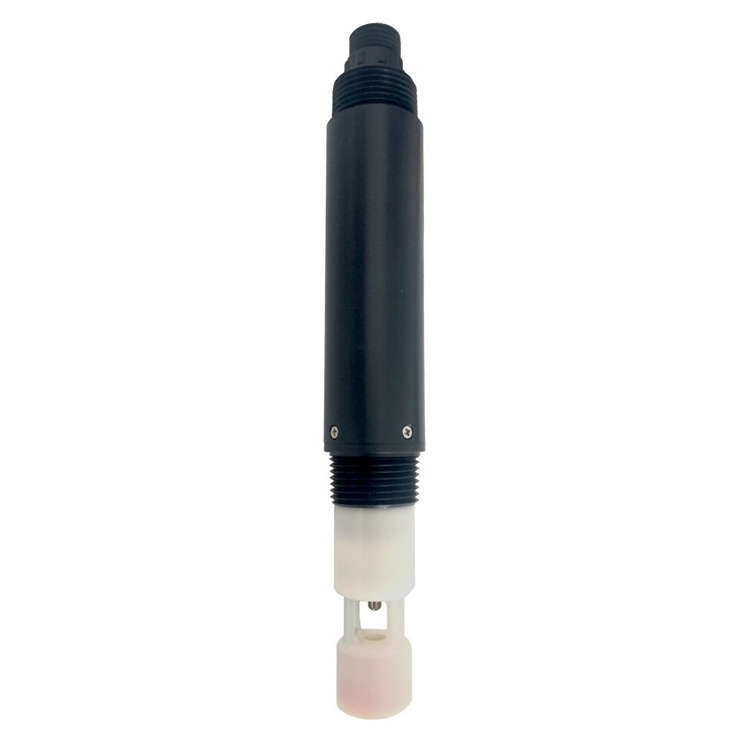
Figure 2. NiuBoL digital salinity probe requiring model-specific wiring and register decoding.
For a soil probe, the sensing element must keep good contact with the surrounding soil. An air gap of a few millimeters around FDR electrodes biases the reading in a way no register scaling can correct, because the instrument measures the gap as much as the soil. An IP68 rating permits continuous burial but does not guarantee contact.
Continuous measurement is limited to medium temperature ≤ 60°C on the level transmitter, and the supply must stay within DC 10–30 V. Log ambient and medium temperature beside the first reading so a later bias can be traced to a condition rather than argued about.
When one point in a field sensor deployment goes silent or lies, work the cheapest cause outward. The opening 0.75 m on an empty tank is branch two, not a dead sensor; swapping the instrument would have left the same held value on the logger.
No DC 10–30 V at the sensor terminals → check voltage drop along the run, not at the supply.
Reversed RS485 A / B → no valid frame, so the logger holds the last value with a new timestamp, as in the opening case.
Duplicate Modbus address → CRC errors and timeouts because two devices answer the same poll.
Missing 120 Ω termination on a long run → reflections corrupting frames at 115200 bps.
0xFFFF sentinel or a value above the 0–15 mS/cm EC range → over-range, not data.
Plausible but wrong value → compare with a handheld meter for drift or poor electrode contact.
A single sensor cannot detect its own drift. Without an independent reference, a slowly biased probe returns confident, wrong numbers for months; define a comparison interval against a handheld meter and treat any step change the process cannot explain as a fault.
Do not use one point as the only input to an automatic decision without independent confirmation, or where the medium can exceed 60°C, the supply can leave DC 10–30 V, or IP68 immersion and electrode contact cannot be maintained. A single point is the wrong unit for spatial coverage or a closed actuator loop; there the number is a measurement, not a verdict.
Field sensor deployment succeeds when the first reading is reproducible and traceable, not merely present. The register hand-check turns a raw integer into a defensible engineering value; skip it and a plausible wrong number passes unnoticed into the log.
Record model, serial number, Modbus address, baud rate and datasheet revision for the point.
Verify DC 10–30 V at the sensor terminals and cable colors against the two documented versions.
Fit 120 Ω termination at both bus ends on a long run and confirm A / B polarity matches the master.
Read the raw register, apply the scaling formula by hand, and compare with the logger value.
Confirm the selected full range M and the accuracy class on the nameplate, not from the resolution.
Compare against a handheld meter and set the drift-check interval before the data is used.
As a next step in field sensor deployment, commission exactly one sensor with this record, save the raw register and the hand-calculated value together, and repeat the comparison after 72 hours. If the two values diverge, work the fault tree from the supply outward. Confirm every numeric value against the current datasheet / nameplate for your instrument before the point is accepted.
Q1. Why does a powered sensor show a plausible but wrong value?

Figure 3. USB to rs485 adapter.
Most often the RS485 A and B wires are reversed or two devices share one Modbus address, so the master reads a stale or foreign register. Confirm DC 10–30 V at the terminals, then A / B polarity, then a unique address and the 4800 bps default before suspecting the sensing element.
Q2. Is 0.01 mS/cm resolution the same as 0.01 mS/cm accuracy?
No. The EC sensor covers 0–15 mS/cm at 0.01 mS/cm resolution, which is only the last displayed digit. Accuracy is a separate specification: the NBL-L-WLPS is quoted at Accuracy Class 0.5, a full-scale class rather than a 0.5 mm tolerance. Confirm the class and its convention on the current datasheet.
Q3. How do I hand-verify a Modbus register reading?
Take raw R = 750 with a 0–1500 count range and 0.01 mS/cm scaling: EC = 750 × 0.01 = 7.50 mS/cm, cross-checked as (750 / 1500) × 15 = 7.50 mS/cm. Any R outside 0–1500, a 0xFFFF sentinel, or a timeout is a fault. This is an illustrative calculation based on assumed site values, not a measured field record.
Q4. Do I need 120 Ω termination for one sensor?
Fit 120 Ω at both bus ends on a long run or at high baud rates up to 115200 bps; a short, slow 4800 bps link often works without it. Missing termination shows up as CRC errors and timeouts, not as a clean zero. Confirm the bus length and baud rate against the current datasheet for your instrument.
Q5. Can a 4–20 mA output replace RS485 for a single point?
Yes, when the logger has only an analog input. Scale it with L = (I − 4) × M / 16, so 12 mA on a 0–1000 mm range gives 500 mm. A 3 mA signal usually means a broken wire, not a zero reading. You lose the address and status word, so diagnostics are weaker.
Q6. When should one sensor not be trusted alone?
Do not use a single point as the only input to an automatic decision without independent confirmation, or where the medium can exceed 60°C, the supply can leave DC 10–30 V, or electrode contact cannot be kept. Compare against a handheld meter on a defined interval; a single point cannot detect its own drift.
One rule to carry to the next field sensor deployment
A field sensor deployment is accepted on decoded values, not on a live display. Raw 750 became 7.50 mS/cm only after the scale factor, register address and unit were written down, and the 0.01 mS/cm reporting digit said nothing about error. Power polarity, A/B pair, 120 Ω termination and a unique Modbus address account for most no-response faults, while installation bias needs a ruler rather than a firmware change. Hand-decode one frame, record the six terminal checks, and keep the raw word beside the scaled value for the first week before the point is signed off.
Have a register map or wiring plan to review? Leave the sensor models, bus length and baud rate in a message on our contact page; we can work through the scaling and termination checks with you.
Related recommendations
Sensors & Weather Stations Catalog
 Agriculture Sensors and Weather Stations Catalog-NiuBoL.pdf
Weather Stations Catalog-NiuBoL.pdf
Agriculture Sensors Catalog-NiuBoL.pdf
Water Quality Sensor Catalog-NiuBoL.pdf
Related products
 Combined air temperature and relative humidity sensor
 TDR Soil Moisture & Temperature Sensor for irrigation| RS485 |4-20mA| NBL-S-THR
 Soil pH sensor RS485 soil Testing instrument soil ph meter for agriculture |NBL-S-PH
 Wind Speed sensor Output Modbus/RS485/Analog/0-5V/4-20mA
 Tipping bucket rain gauge for weather monitoring auto rainfall sensor RS485/Outdoor/stainless steel
 Pyranometer Solar Radiation Sensor 4-20mA/RS485


Screenshot, WhatsApp to identify the QR code
WhatsApp number:+8615367865107
(Click on WhatsApp to copy and add friends)

