





— Blogs —
—Products—
 Consumer hotline +8618073152920
WhatsApp:+8615367865107
Address:Room 102, District D, Houhu Industrial Park, Yuelu District, Changsha City, Hunan Province, China
Product knowledge
Time:2026-11-09 09:00:00 Popularity:9
An irrigation control loop closes the path from a soil moisture reading to a valve that opens for a measured interval and then proves it moved. One full sequence — sample every 30 s, compare against a deadband, energize a relay for a 90 s minimum run, read back a feedback contact — takes about 100 seconds from trigger to verified state.
The commissioning log looked complete. Volumetric water content fell to 17.4%, the controller issued an open command at t = 2 s, the feedback bit read OPEN at t = 5 s, and the cycle closed at t = 499 s with a 497 s valve-on time. The tank level transmitter recorded no drawdown. The loop had trusted a command echo instead of a physical consequence, and every number in the log stayed consistent until the water never moved.
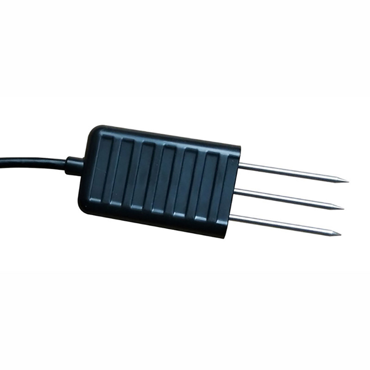
Figure 1. Soil Temperature Moisture Sensor Modbus RS485 FDR Soil Tester For Precision Agriculture — NBL-S-TM.
An auxiliary contact wired to the relay coil, not to the valve stem, reports OPEN whenever the coil is energized. It is an echo of the electrical command, so it cannot detect a stuck solenoid, a shut isolation valve or an empty tank, and it will keep agreeing with the controller for the whole event.
The fix is not more logic. It is a feedback source mechanically tied to the actuator, plus a second independent signal, tank level, that confirms water actually left the system. Both have to agree before an event is written as delivered.
Do not close an irrigation control loop on a channel whose display increment is finer than its error budget. A soil channel showing 0.1% VWC steps against the 0.5% deadband used in this log is offering a reporting digit, not a decision threshold; tripping on it would be thresholding noise instead of measuring a change in soil water.
Greenhouse practice draws the boundary sharply. Automatic insulation, ventilation and light control with history logging are achievable, but humidity regulation still needs manual intervention. A 6-point VWC hysteresis band does not change that: it is a soil limit, not a climate recipe, and a single loop should not be sold as one.
An irrigation control loop reading only air temperature, humidity and CO2 has no input for leaf temperature, photosynthesis or transpiration. Its 18% / 24% VWC thresholds describe soil, not the crop, so the loop cannot claim to optimize plant growth or to replace an operator watching the canopy.
Rule sets drawn from expert knowledge cover only conditions the expert has already seen. With a 90 s minimum run time and a three-poll comms timeout, an unmodeled combination stalls rather than adapts; the loop repeats its last valid state until someone intervenes.
A control decision also has to be local. With a 30 s poll and a 90 s minimum run, an ON decision sent on a remote round trip can arrive after the valve was due to close, so the sequence and its fail-safe belong in the panel controller rather than in a cloud rule that depends on the uplink.
Q1. Can a control loop work without a feedback contact?
No. Without an auxiliary contact or a discrete feedback register, the controller knows it sent a command, not that the valve moved, so a stuck coil produces a logged but undelivered event. Budget a 5 s verification window and one retry before lockout, then confirm the de-energized position on the valve nameplate.
Q2. Why is 20% VWC not an irrigation threshold?
Around 20% VWC is a measurement reference, not a trigger. The ON decision belongs to a lower threshold such as 18% and the OFF target to 24%, with a 6 percentage point band between them. Treat the displayed number as a reading to be filtered, not as a setpoint the controller should chase.
Q3. How many actuators can one irrigation control loop drive?
A large greenhouse may coordinate more than a dozen actuators, from natural ventilation and external shading to cooling pads, forced fans, CO2 enrichment, misting and supplemental lighting. This loop drives exactly one of them through one relay output and one feedback bit; the rest belong to other interlocks.
Reconstruct the irrigation control loop cycle from stored timestamps before touching a single setpoint. The table below is the acceptance record for one event; each row is a controller observation at a known time, not an instrument specification, and the sequence is what an auditor replays after a delivered-volume dispute.
Steps 4 and 8 disagree. That single mismatch is the entire diagnosis: the feedback bit reported an open valve at t = 5 s while the tank level showed no drawdown at t = 499 s. The loop verified its own command but never its own effect on the water.
The manual / auto switch is logged on the same timeline. An operator override at any step must appear as a timestamped row with the feedback state, otherwise the event log cannot be reconstructed later, and a manual action during the 497 s event would look exactly like an automatic one.
The 100-second figure quoted at the start describes the shortest verifiable cycle, where the 90 s minimum run dominates the sum of a 30 s poll, a 2 s relay delay and a 5 s feedback window. A computed 497 s dose simply replaces that floor; the poll, relay and feedback delays stay the same.
Every number in the irrigation control loop log is a site parameter chosen for this crop and soil, not a sensor specification. Four of them govern whether the valve moves at all, one governs what happens when the bus goes quiet, and none of them can be read off a product nameplate.

Figure 2. Soil Moisture Temperature sensor.
These are assumed site values and typical engineering reference values; check against the current datasheet / nameplate for your instrument. Wrong: a hardwired 4–20 mA trip amplifier switches the relay at one current and has no memory. Right: a Modbus-based loop reads a scaled register, applies deadband and hysteresis in logic, and logs the decision with diagnostics.
The 497 s dose in this irrigation control loop was not a guess, and it was not a fixed timer copied from another zone. It is the water volume needed to lift the root zone from 17.4% to 22% VWC, divided by the flow the valve can actually deliver at this site under its measured supply pressure.
Input values, all assumed site values: root-zone depth d = 0.30 m, wetted area A = 20 m², valve flow Q = 2.0 m³/h. Formula chain: ΔVWC = 0.22 − 0.174 = 0.046; water depth Δd = 0.046 × 0.30 = 0.0138 m; volume V = 0.0138 × 20 = 0.276 m³; time T = 0.276 / 2.0 = 0.138 h = 497 s. Result: 497 s, above the 90 s floor and below the 600 s guard, so no clamp applies.
Boundary conditions: uniform infiltration with no runoff or evaporation, Q constant and confirmed against the valve or flowmeter nameplate, and a valid feedback signal. If Q falls to 1.6 m³/h from a clogged filter, the same 497 s delivers only 0.221 m³, about 20% less water. This is an illustrative calculation based on assumed site values, not a measured field record.
An irrigation control loop only sees what its I/O map defines. Confirm each point after the dose arithmetic, because a correct calculation on a wrong channel still delivers nothing, which is exactly how the failed cycle above was produced. The table below doubles as the commissioning sign-off sheet.
A digital path keeps the raw word and diagnostic flags, so a timeout is distinguishable from a dry reading. A 4–20 mA or 0–5 V channel hides both inside a current; use it only where the panel has no Modbus master, and confirm the input range on the current datasheet.
Where an analog input is unavoidable, agree the selected full measuring range with the receiving panel before commissioning and record it in the I/O table above. A range mismatch shifts every value by the same factor, and no amount of deadband tuning will reveal it; hand-decode one raw register and compare it with the scaled value in the log.
The failed irrigation control loop cycle had a correct dose, a correct dose time and a correct OPEN bit. It failed because feedback was wired to the command. Move that contact to the valve stem, add a tank-level check, and the same 497 s event becomes a delivered one instead of a plausible log entry.

Figure 3. Smart Data Collector.
As a next step, re-run one zone of this irrigation control loop with a feedback-equipped valve, log at least 72 hours of VWC, command, feedback and tank level, and use the logged mismatches to set final retry and lockout counts. Confirm every numeric value against the current datasheet and the valve nameplate for your instrument before you lock the site configuration.
Q4. What does a 90 s minimum run time actually protect?
It protects the pump and the valve from rapid cycling, and it exceeds the 5 s feedback verification window used in the log. A 90 s floor with a 300 s minimum off time and a 600 s maximum bounds how often the actuator moves. Confirm the final value against the valve and pump nameplates for your instrument.
Q5. Which RS485 baud rate should the loop use?
Keep the 4800 bps default unless the whole bus is reconfigured together; the configurable range is 1200–115200 bps. A device left at 4800 bps while the master runs 115200 bps will never answer, and the resulting timeout looks like a dry reading. On a long cable run, terminate both ends with 120 Ω resistors.
Q6. How is a fail-closed valve verified before commissioning?
De-energize the coil and confirm the valve is mechanically shut, then command open and confirm OPEN within 5 s. Simulate three consecutive no-response polls, 90 s at a 30 s interval, and confirm the controller forces CLOSED and raises an alarm. Record the de-energized position from the valve nameplate.
The one check that settles an irrigation control loop
An irrigation control loop is only closed when a physical consequence confirms the command. In the 497-second cycle examined here, the OPEN bit, the dose time and the tank level disagreed, and the tank level was the only signal that could show no water had moved. A 90 s minimum run and a 5 s feedback window bound the sequence, but neither substitutes for a contact on the valve stem. Before accepting a zone, re-run one cycle with stem feedback and log VWC, command, feedback and tank level together for at least 72 hours; use the mismatches, not the datasheet, to set retry and lockout counts.
Designing an irrigation control loop for a specific block? Send the valve type, feedback contact and logger interface through our contact page, and our engineers will help you check the I/O list and the fail-safe sequence against your hardware.
Prev:Ambient Air Quality Monitor: Siting, Calibration, 24h Data
Next:no more
Related recommendations
Sensors & Weather Stations Catalog
 Agriculture Sensors and Weather Stations Catalog-NiuBoL.pdf
Weather Stations Catalog-NiuBoL.pdf
Agriculture Sensors Catalog-NiuBoL.pdf
Water Quality Sensor Catalog-NiuBoL.pdf
Related products
 Combined air temperature and relative humidity sensor
 TDR Soil Moisture & Temperature Sensor for irrigation| RS485 |4-20mA| NBL-S-THR
 Soil pH sensor RS485 soil Testing instrument soil ph meter for agriculture |NBL-S-PH
 Wind Speed sensor Output Modbus/RS485/Analog/0-5V/4-20mA
 Tipping bucket rain gauge for weather monitoring auto rainfall sensor RS485/Outdoor/stainless steel
 Pyranometer Solar Radiation Sensor 4-20mA/RS485


Screenshot, WhatsApp to identify the QR code
WhatsApp number:+8615367865107
(Click on WhatsApp to copy and add friends)

