

— Blogs —
—Products—
 Consumer hotline +8618073152920
 WhatsApp:+8615367865107
Address:Room 102, District D, Houhu Industrial Park, Yuelu District, Changsha City, Hunan Province, China
Product knowledge
Time:2026-06-29 11:33:45 Popularity:22
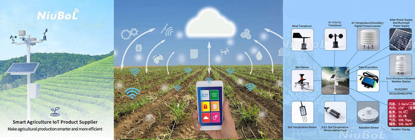
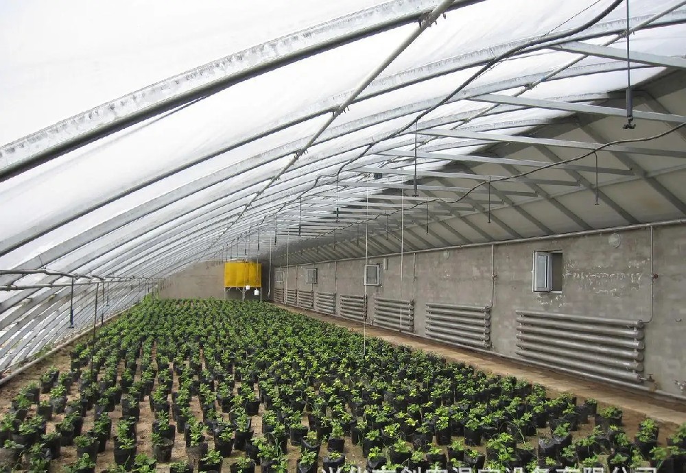
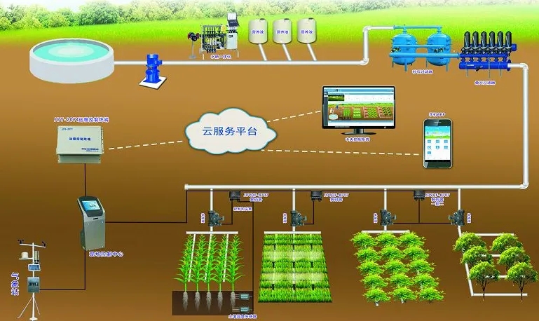
A greenhouse automatic control system is built to observe environmental variables and operate equipment according to management rules. It is used in commercial greenhouses, agricultural demonstration parks, scientific research sites, teaching greenhouses, and high-value crop facilities. The system may monitor weather, indoor climate, soil status, light, CO2, rainfall, solar radiation, UV, leaf wetness, and other variables while controlling windows, film rollers, fans, wet curtains, lights, irrigation, or fertilization equipment.
For procurement, the key issue is system boundary. Some projects need only monitoring and alarms. Some require remote manual control. Others require automatic control with safety interlocks. A clear boundary prevents under-quoted systems and avoids forcing a small monitoring controller to handle electrical loads that should be managed by a power cabinet or PLC.
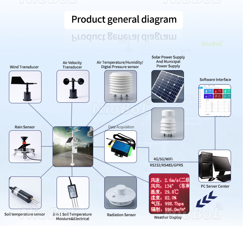
Greenhouse automation has moved from simple analog instruments to distributed control and computer-based multi-factor management. Modern systems use sensors, controllers, communication interfaces, storage devices, and remote platforms to support all-weather operation. This development matters for buyers because an automatic greenhouse system is no longer only a timer or a thermostat. It is a data and control platform that must match the crop process.
The source technical material describes greenhouse systems that collect many environmental elements, provide relay outputs for several equipment channels, support large LCD display, store data through SD or U disk, and communicate through RS232, RS485, USB, and Ethernet. These functions should be evaluated as project capabilities, not isolated features.
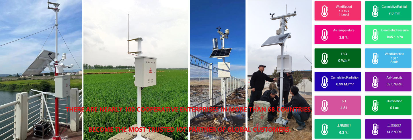
A complete greenhouse system may collect outdoor weather, indoor crop climate, and soil or substrate data. Outdoor variables help protect the structure and support ventilation decisions. Indoor variables explain crop environment. Soil variables explain root-zone water and fertilizer status. The design should separate these groups because they are used for different decisions.
| Variable Group | Typical Measurements | Project Use |
|---|---|---|
| Outdoor weather | Wind speed, wind direction, rainfall, pressure, solar radiation, UV | Supports window protection, weather records, and storm response |
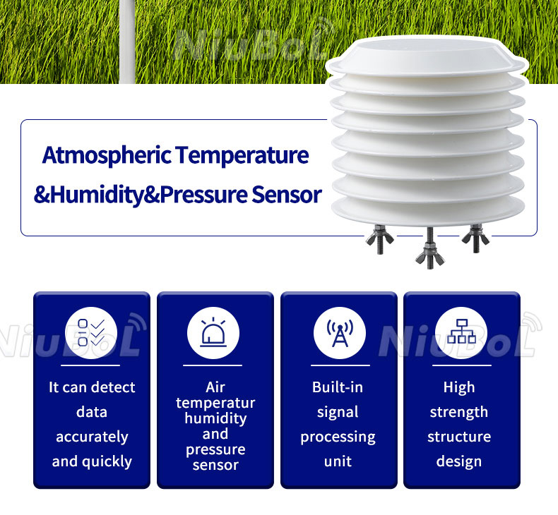
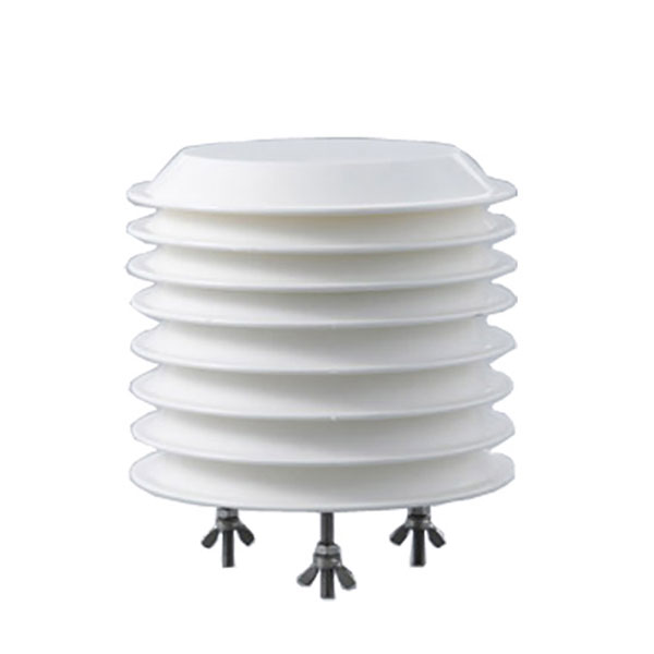
| Indoor climate | Air temperature, relative humidity, dew point, CO2, illuminance | Supports crop climate control and disease-risk review |
| Soil or substrate | Soil temperature, moisture, EC, water potential, heat flux | Supports irrigation, fertigation, and root-zone analysis |
| Crop surface | Leaf wetness or related sensors by configuration | Supports disease-risk assessment in humid periods |
| Controller outputs | Up to 16 relay outputs in suitable controller configurations | Controls or signals multiple equipment channels |
| Data storage | SD or U disk continuous storage by configuration | Provides local records for operation and reporting |
| Communication | RS232, RS485, USB, Ethernet by configuration | Supports local connection, network control, and integration |
| Remote access | Ethernet or wireless controller options | Supports multi-greenhouse network and remote management |
The controller sits between field sensors and actuators. It receives sensor values, compares them with configured rules, records data, displays status, and sends control signals. It should not be confused with the power distribution cabinet. The controller decides or signals; the electrical cabinet provides safe switching, protection, and power wiring for motors, pumps, fans, and lights.
When RS485 greenhouse sensors are used, the controller or acquisition host must poll each address and convert register values into engineering units. For Ethernet or internet remote control, network security, login permission, and data backup should be part of the project discussion.
Automatic control can improve response speed, but it can also create risk if poorly defined. Windows should not open under high wind. Wet curtains should not operate without fan logic. Irrigation should not run if the pump protection circuit reports a fault. Supplemental lights may need time schedules and thermal protection. For this reason, automatic control rules should be reviewed with the greenhouse equipment list and electrical contractor.
A staged deployment is often practical. First, install monitoring and data storage. Second, add alarms and remote manual control. Third, enable automatic rules after operators understand the data and equipment response. This workflow gives the buyer useful records before relying on automation.
Field environment challenge: Humidity, temperature, and soil moisture can change quickly under ventilation and irrigation events.
System integration scheme: Use indoor climate sensors, soil sensors, a controller with relay outputs, and platform records for equipment status.
User value: Operators can link climate changes to fan, curtain, wet pad, or irrigation actions and improve daily management.

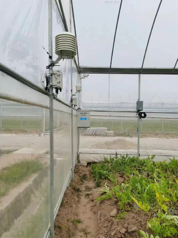
Field environment challenge: Projects require visible data, remote access, and clear demonstration of automation logic.
System integration scheme: Use multiple sensors, LCD display, storage, Ethernet or wireless upload, and documented control channels.
User value: Visitors and managers can see measurable greenhouse operation instead of only equipment appearance.
Field environment challenge: Research requires traceable environmental records and stable sampling intervals.
System integration scheme: Store data through SD or U disk, export records, and keep sensor names consistent by experiment zone.
User value: Teachers and researchers can use real curves for teaching, comparison, and project reports.
Field environment challenge: Irrigation decisions are affected by soil moisture, EC, crop stage, and weather conditions.
System integration scheme: Combine soil sensors with controller outputs to signal valves or irrigation equipment through a protected cabinet.
User value: The project reduces blind watering and supports documented fertigation management.
Separate sensor signal wiring from motor and pump power wiring.
Create a channel table for each relay output, including controlled device, voltage, current, and safety interlock.
Define manual override and emergency stop behavior before enabling automatic control.
Record RS485 addresses, register maps, cable lengths, and cabinet terminal numbers.
Verify local storage and data export before relying on remote platform records only.
Use weather protection and grounding for outdoor sensors and communication lines.
A useful inquiry should include greenhouse dimensions, crop type, equipment list, desired sensors, number of control channels, communication requirement, platform access requirement, and whether the buyer expects only monitoring or automatic control. If the project involves existing equipment, provide control cabinet photos and electrical drawings where available.
For acceptance, require a sensor list, wiring diagram, relay channel list, platform screenshot, alarm test result, data export sample, and operation training record. These deliverables help the owner operate the system after installation and reduce disputes about whether the supplied equipment matches the project scope.
A: It is a system that collects greenhouse environmental data and controls or signals equipment such as windows, fans, wet curtains, lights, irrigation, and fertilization devices according to configured rules.
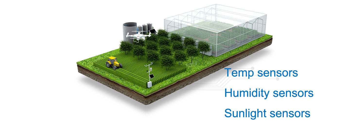
A: Air temperature, relative humidity, light, CO2, soil moisture, and soil temperature are common first-stage variables. Additional variables depend on crop type and control objectives.
A: Only if the number of outputs, electrical interface, power cabinet design, and safety requirements match. Large motors and pumps usually need contactors, protection circuits, or PLC integration.
A: RS485 sensors are common because they support industrial communication, multi-device addressing, and integration with greenhouse controllers, gateways, PLCs, and monitoring platforms.
A: Monitoring records data and may generate alarms. Automatic control uses rules to operate or signal equipment. Automatic control requires more careful safety and electrical design.
A: Each relay output should have a channel name, controlled device, operating condition, manual override rule, electrical interface, and safety interlock requirement.
A: Yes. Local SD or U disk storage can preserve records during network failure and provide an independent data source for acceptance or maintenance review.
A: Test every sensor, RS485 address, display value, storage record, upload function, alarm rule, relay output, manual override, and emergency stop behavior.
A: Yes. It is suitable when sensor names, sampling intervals, storage, export format, and calibration records are managed carefully.
A: Send greenhouse size, crop, sensor requirements, actuator list, expected control level, power condition, communication method, platform needs, and existing cabinet information.
A greenhouse automatic control project should end with documents that the owner can use after the installation team leaves. These files should include a sensor list, controller channel table, relay output table, cabinet terminal diagram, communication settings, platform account list, alarm rule list, and a short operation procedure. Without these records, later maintenance depends on memory rather than engineering documentation.
The acceptance file should also record which functions are automatic and which functions remain manual. This is important because buyers sometimes assume that every connected device is fully automatic. A clear file prevents misunderstanding and helps operators know which actions still require human confirmation.
Using one indoor temperature sensor to represent several different greenhouse zones.
Connecting actuator control before confirming electrical load and safety interlock requirements.
Giving sensors unclear names such as temperature 1, temperature 2, without greenhouse and zone information.
Ignoring local storage and relying only on cloud upload in sites with unstable communication.
Setting one threshold for all seasons instead of adjusting rules by crop stage and operating period.
A greenhouse controller is suitable when the project mainly needs environmental monitoring, relay signals, data storage, and routine equipment logic. PLC integration becomes more suitable when the greenhouse already has complex motor control, interlocking, frequency converters, multiple cabinets, or strict electrical sequencing. In many projects, the practical design is combined: sensors and records are handled by the monitoring system, while heavy actuator control is handled by the existing electrical automation cabinet.
A greenhouse automatic control system should be designed around monitored variables, control objects, communication paths, storage, and safety boundaries. NiuBoL greenhouse monitoring and control configurations can support RS485 sensors, local display, data storage, remote communication, and multiple relay channels by project requirement. The procurement decision should focus on usable operation logic, documented integration, and clear acceptance records.
Prev:Smart Greenhouse Solution for Sensor Monitoring, Modbus Control, and Cloud Management
Next:no more
Related recommendations
Sensors & Weather Stations Catalog
 Agriculture Sensors and Weather Stations Catalog-NiuBoL.pdf
Weather Stations Catalog-NiuBoL.pdf
Agriculture Sensors Catalog-NiuBoL.pdf
Water Quality Sensor Catalog-NiuBoL.pdf
Related products
 Combined air temperature and relative humidity sensor
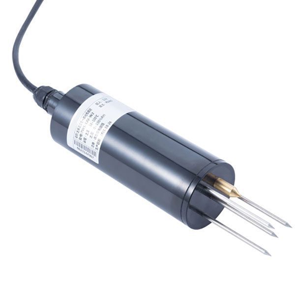 Soil Moisture Temperature sensor for irrigation|NBL-S-THR
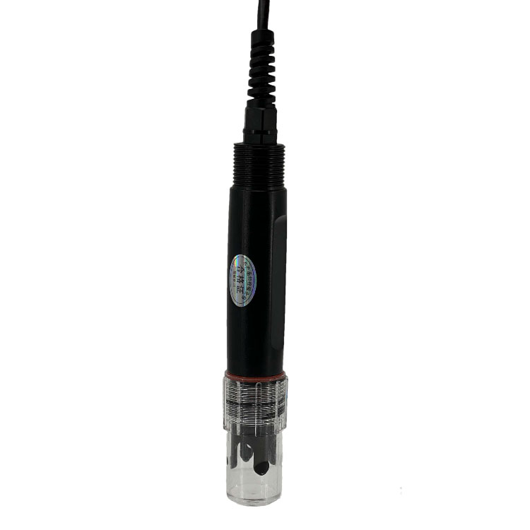 Soil pH sensor RS485 soil Testing instrument soil ph meter for agriculture |NBL-S-PH
 Wind Speed sensor Output Modbus/RS485/Analog/0-5V/4-20mA
 Tipping bucket rain gauge for weather monitoring auto rainfall sensor RS485/Outdoor/stainless steel
 Pyranometer Solar Radiation Sensor 4-20mA/RS485

Screenshot, WhatsApp to identify the QR code
WhatsApp number:+8615367865107
(Click on WhatsApp to copy and add friends)
