





— Blogs —
—Products—
 Consumer hotline +8618073152920
WhatsApp:+8615367865107
Address:Room 102, District D, Houhu Industrial Park, Yuelu District, Changsha City, Hunan Province, China
Product knowledge
Time:2026-08-14 09:04:00 Popularity:283
Quick Answer: COD sensor sampling is unreliable when a bypass stops delivering current process water, even if the probe continues returning plausible numbers. Use a separate indication of sample delivery, exclude stagnant-water periods from normal process interpretation, and verify flushing after restart. A pump command or a successful Modbus response does not prove that fresh water has reached the optical path.

A stopped pump, blocked intake or closed valve can leave water around an immersed optical probe. The instrument may still communicate normally because it remains powered and wet. Its reading then describes the trapped sample, not necessarily the current plant discharge or tank condition.
The installation question is therefore more specific than whether to choose a tank or cabinet: what confirms delivery to the measurement point, and how will the records be labeled when delivery is lost? The same issue applies to a conductivity probe in the shared sample path; a stable EC value is not proof of flow.
| State | What has been established | Recommended record treatment |
|---|---|---|
| Normal acquisition | Delivery verified; sample and instrument checks passed | Record process values with the relevant time basis |
| Delivery lost | Sample path cannot be relied on | Mark values unavailable or stale; do not record zero as a substitute |
| Restart and flushing | Delivery has resumed but retained water may remain | Keep values flagged until the validated flush and stability checks pass |
| Cleaning or service | Probe or water path is under maintenance | Separate service records from ordinary process interpretation |
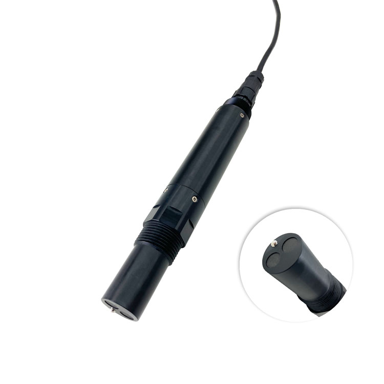
These are proposed controller states, not claimed built-in functions of the NBL-WQ-COD. A PLC, RTU or data logger must implement them with suitable inputs. Select a sample-delivery indication appropriate to the assembly and test the failure modes it can and cannot detect. A running pump can still face an empty intake or a downstream blockage.
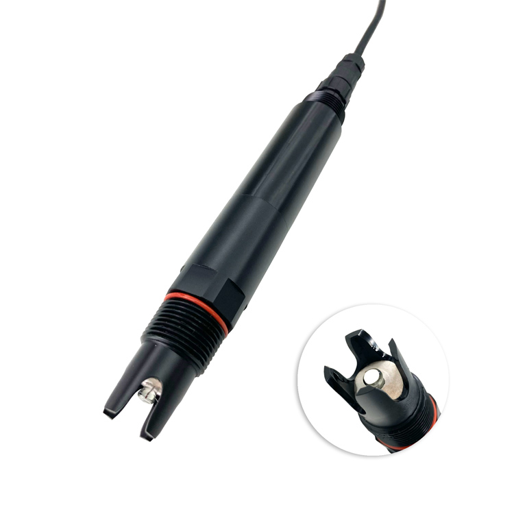
Check other sensors on the same path individually. A pH probe might remain immersed in retained liquid while a different part of the assembly drains. Shared pump status does not establish immersion, representative sampling or readiness for every channel.
For a simple screening calculation, divide the retained water volume by the measured delivery flow: nominal residence time = volume / flow. For example, 3 L of retained volume at 0.5 L/min gives 6 minutes. This is an illustrative calculation, not an approved flushing time or an actual project result.
Include the intake tube, fittings, vessel and other significant retained volumes. Mixing, dead legs, variable flow and deposits mean that exchanging one nominal volume does not prove complete replacement. Measure delivery at the relevant operating condition and establish the required recovery period through a controlled commissioning test.
Record the time at which delivery resumes, when newly delivered water reaches the probe and when readings become suitable for the intended decision. Take comparison samples at the same measurement location and align them with that time basis. For the broader layout choice, see direct immersion versus a sample bypass.
The PH-4S probe shown below requires its own installation limits and service checks. When several instruments occupy one vessel, the water path and mounting arrangement must satisfy all of them, rather than treating the vessel as an unrestricted universal holder.
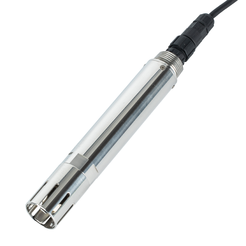
The NiuBoL NBL-WQ-COD is an immersion instrument using dual-wavelength UV absorption. Its turbidity compensation addresses part of the optical interference; it cannot correct a stale sample, and it does not establish equivalence to every laboratory COD method.
| NBL-WQ-COD item | Specification | Sampling consequence |
|---|---|---|
| COD configurations | 0-200 or 0-500 mg/L equivalent KHP | Choose for the expected water and verify the process relationship |
| COD accuracy / resolution | +/-5% FS / 0.1 mg/L | Display resolution is not method agreement |
| Associated turbidity ranges | 0-100 or 0-200 NTU by configuration | Review the actual solids conditions before selection |
| Operating conditions | 0-45 C; pressure below 0.1 MPa | Do not expose an immersion assembly to unverified pump pressure |
| Supply / consumption | 12-24 VDC; 0.3 W at 12 V | Include pumps and other equipment separately |
| Output / protection | RS485 Modbus RTU / IP68 | Communication and immersion do not confirm sample delivery |
| Housing / cable | 316L stainless steel; standard 5 m shielded cable | Confirm jacket and liquid compatibility; protect joints |
| Cleaning | Integrated cleaning brush | Keep brush clearance and access; inspect deposits in the water path separately |
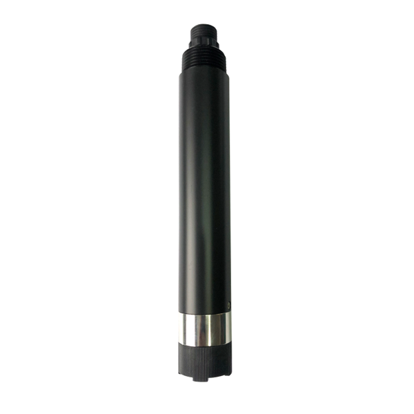
If the station also measures dissolved oxygen, consider whether the sample route changes the oxygen condition before it reaches that probe. The separate DO-4A instrument below cannot establish that the COD sample represents current discharge, nor can a valid COD record validate the oxygen channel.
The sensor may be reading retained water whose condition is changing, or its optical surface may be affected by bubbles or deposits. Check sample delivery and probe condition before interpreting the change as current process behavior.
No. It confirms an equipment state, not necessarily water arrival. Verify delivery through an appropriate independent check and include blocked-intake, closed-valve and low-water conditions in commissioning.
Not necessarily. The volume/flow calculation is an estimate. Mixing and stagnant sections can extend replacement; validate recovery in the actual assembly and retain that test with the operating procedure.
First investigate flushing, bubbles, optical fouling and timestamp alignment. Calibration cannot make stale or unrepresentative water equivalent to the current process sample.
Use an explicit quality or availability state with a timestamp. Do not substitute zero COD or present a held last value as a new process observation. Test the downstream alarm behavior for this state.
Provide the source location, tube dimensions, vessel volume, measured flow, pump schedule, expected COD/turbidity and pressure. Include the required time-to-decision so the sampling route and controller logic can be reviewed together.
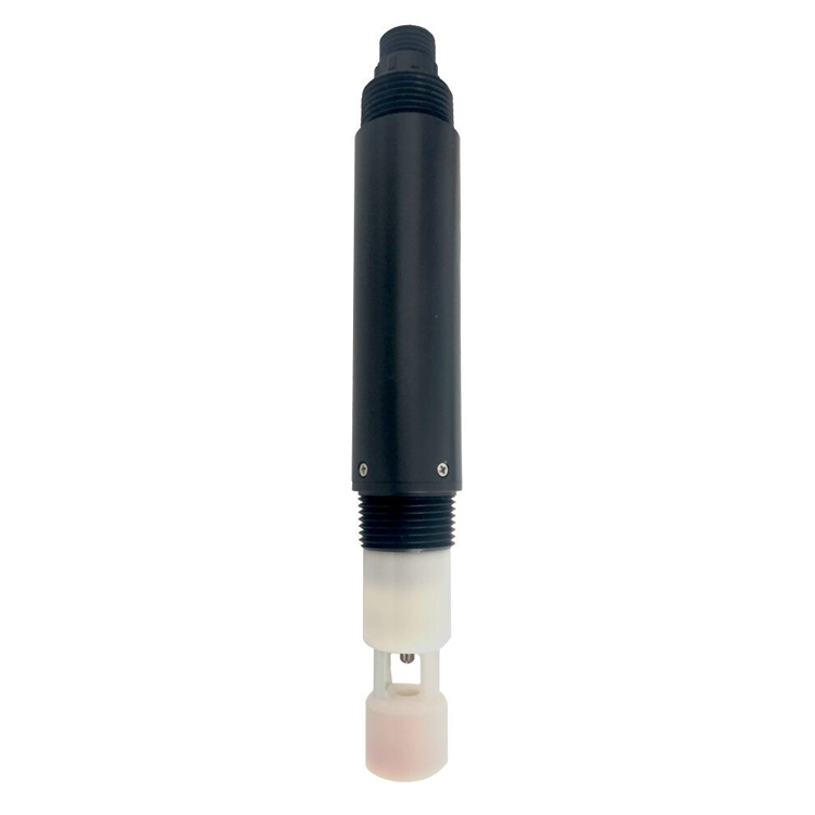
COD sensor sampling needs proof that representative water reaches the instrument. Treat sample loss and restart as distinct operating states, validate the flush rather than guessing a fixed delay, and keep other water-quality channels independent. A salinity probe or any other responding instrument is not a substitute for checking the COD sample path.
Prev:Insect Monitoring System Solar Power Maintenance
Next:Online Water Quality Sensor Mounting: Design a Retrievable Multi-Probe Rack
Related recommendations
Sensors & Weather Stations Catalog
 Agriculture Sensors and Weather Stations Catalog-NiuBoL.pdf
Weather Stations Catalog-NiuBoL.pdf
Agriculture Sensors Catalog-NiuBoL.pdf
Water Quality Sensor Catalog-NiuBoL.pdf
Related products
 Combined air temperature and relative humidity sensor
 TDR Soil Moisture & Temperature Sensor for irrigation| RS485 |4-20mA| NBL-S-THR
 Soil pH sensor RS485 soil Testing instrument soil ph meter for agriculture |NBL-S-PH
 Wind Speed sensor Output Modbus/RS485/Analog/0-5V/4-20mA
 Tipping bucket rain gauge for weather monitoring auto rainfall sensor RS485/Outdoor/stainless steel
 Pyranometer Solar Radiation Sensor 4-20mA/RS485


Screenshot, WhatsApp to identify the QR code
WhatsApp number:+8615367865107
(Click on WhatsApp to copy and add friends)

