





— Blogs —
—Products—
 Consumer hotline +8618073152920
WhatsApp:+8615367865107
Address:Room 102, District D, Houhu Industrial Park, Yuelu District, Changsha City, Hunan Province, China
Product knowledge
Time:2026-08-14 09:03:00 Popularity:323
Quick Answer: Insect monitoring system solar power maintenance starts with the complete equipment load and evidence of charging, not a panel wattage label. Inspect the panel, battery, controller and cabling separately from the trap and image path. A cabinet may remain online while sample processing is interrupted. Check a full operating cycle and preserve interruption times so an energy fault does not become a false zero-catch record.
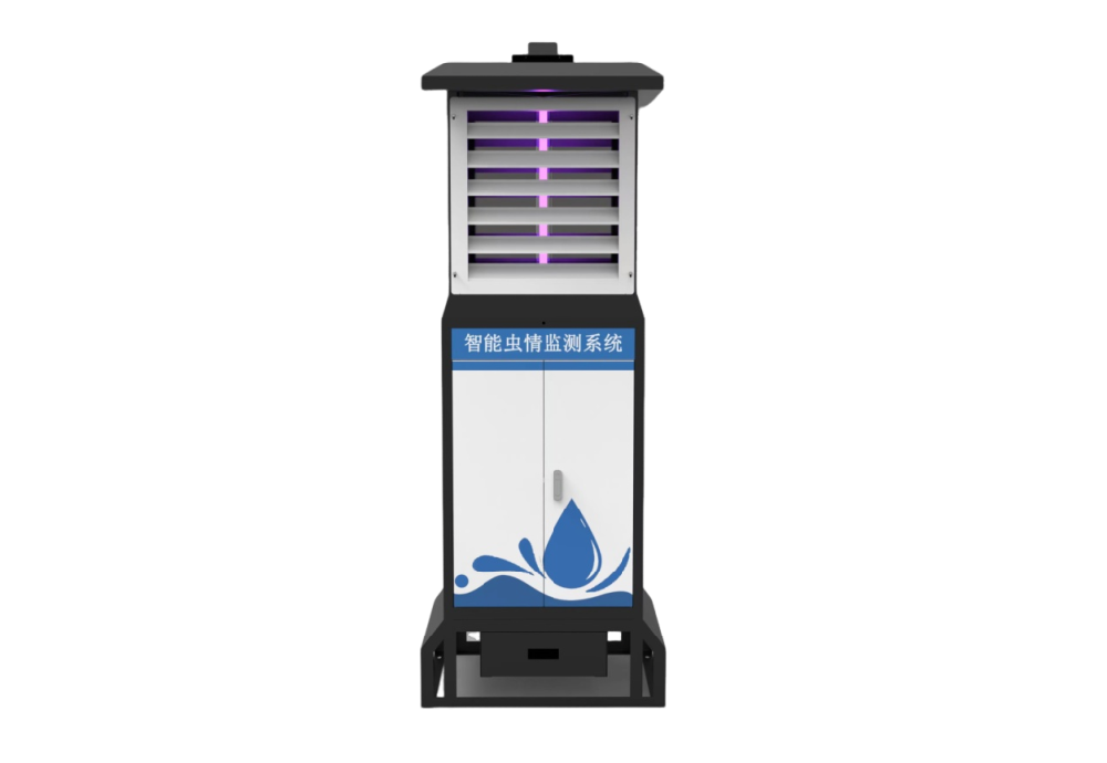
Obtain the duty cycle and consumption of the exact equipment. Include nighttime operation, image capture, communications and standby rather than using the sensor's lowest power figure. State the required autonomy and review the battery and solar arrangement against the actual site.
A panel rating alone does not establish station autonomy. Shade, orientation, contamination and seasonal sunlight affect charging, while battery temperature and ageing affect available storage. Confirm the design assumptions with the equipment supplier.
The NBL-IoT-SRPMS pipeline-vibration cabinet provides a useful example of why the load must be identified carefully. Its 18 W attraction lamp is only one component. Maximum monitoring power is 225 W and standby power is no more than 15 W. Heating and sample handling can therefore change the energy budget substantially compared with a simple insect-killing light.
| Information to obtain | Why maintenance needs it | Common wrong inference |
|---|---|---|
| Active-state power and duration | Identifies the load during processing, imaging and transmission. | Lamp wattage is the whole cabinet load. |
| Battery voltage and usable capacity | Allows available energy to be expressed in Wh. | An Ah rating alone establishes autonomy. |
| Sleep or standby schedule | Accounts for energy use between sampling periods. | Standby means no consumption. |
| Controller and battery settings | Defines the permitted charging and low-voltage behavior. | All battery chemistries use the same thresholds. |
| Protection and connections | Identifies outdoor enclosure, connector and cable-entry requirements. | The cabinet rating automatically covers every field joint. |
For an explicitly simplified energy example, assume 225 W for 0.5 hour and 15 W for the remaining 23.5 hours: the total is 465 Wh/day. These assumed durations are not the cabinet's specified duty cycle. For an illustrative 24 V, 50 Ah battery, nominal energy is 1200 Wh; assuming 80% usable capacity and 90% delivery efficiency leaves 864 Wh, approximately 1.86 days at that example load. None of these assumptions establishes the autonomy of a purchased solar package.
Autonomy and recharge are separate questions. In another illustrative calculation, a 400 W array receiving three equivalent full-sun hours with a 0.70 production derating yields 840 Wh at the controller-output basis. Against the example 465 Wh load, 375 Wh remains before battery charging losses and any omitted loads. These sunlight and derating assumptions are not a site survey or a guaranteed daily output.
If the battery was depleted during several poor days, the first sunny day may not restore it. Examine cumulative recovery over the actual operating schedule rather than declaring the fault resolved when the controller briefly shows charging. Reducing the observation schedule also changes monitoring coverage; retain that change with the catch record.
A useful service record therefore includes more than a midday voltage photograph. Where the controller provides them, review daily charge and load energy, low-voltage events and time spent in charging states. Check whether the reported quantities are measured or estimated and whether they reset after a restart. A different counter reset can otherwise resemble a sudden deterioration in solar performance.
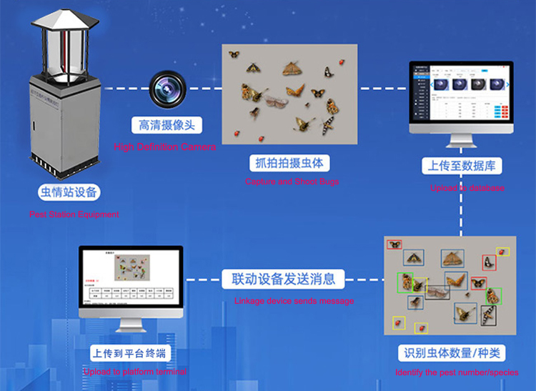
The monitoring location should represent the target crop and pest activity. A place with convenient sunlight may be unsuitable for representative trapping. Where necessary, review cable routes and a separate panel position rather than moving the observation point without considering its biological purpose.
Check shade at different times and seasons. A panel can look unobstructed during a morning service visit yet be shaded through the useful afternoon period. Growth of nearby vegetation or a new structure can change charging after an initially satisfactory installation.
If the panel must be separated from the cabinet, verify cable length, conductor size and protection with the electrical design. Excessive voltage drop or an unsuitable connector can reduce charging even when the panel is clean. Do not improvise a longer battery cable or bypass protective devices to recover a failing installation.
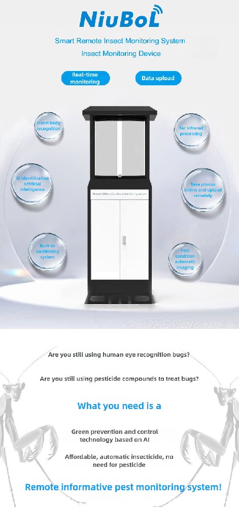
Record battery voltage or state information provided by the equipment, charging behaviour and outage events. A declining trend can indicate shading, dirt, a loose connection, increased load or battery deterioration. Inspect the supply before attributing missing images to the network.
Compare observations under similar operating states. Battery voltage during heater operation is not directly comparable with a rested reading after standby. Record the active function and charging state with the measurement. A single voltage reading is not a reliable capacity test for every battery chemistry.
| Observed symptom | Checks that separate causes | Decision to avoid |
|---|---|---|
| Repeated overnight shutdown | Check the complete night schedule, battery condition and charging during the preceding day. | Replacing the modem because images stop arriving. |
| Charge declines after a settings change | Compare heater time, attraction periods, photograph frequency and upload attempts. | Assuming the panel has deteriorated without checking the load. |
| Display works but processing stops | Review low-voltage events and the power available when motors or heating start. | Treating online status as proof of a completed sample. |
| Charging falls on sunny days | Inspect shade, contamination, wiring and controller indications using permitted test procedures. | Changing battery limits before diagnosing the charging path. |
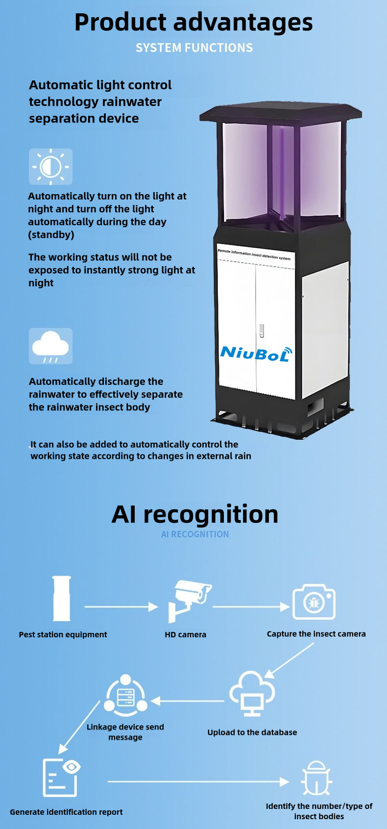
Solar availability does not remove the need to clean the trap, check the attraction method and review the images. Keep service events with the count record. A blocked or damaged collection area can change catch rates even while the electronics remain online.
During commissioning, test a controlled loss of communications and a power restart. Confirm whether records are stored locally, whether timestamps are preserved and how missing data appear. Ask for a demonstration of any buffering or low-battery function included in the order.
After a low-voltage event, inspect which stage was interrupted. Material may remain in the processing chamber or on the board. Verify the next sequence and its record assignment before treating the restarted system as a complete observation. A retransmitted photograph should retain its sampling period rather than receiving a new capture identity.
For RS485 Modbus RTU or other third-party acquisition, obtain the actually implemented interface. A reserved RS485 port is not proof of a readable battery or status register. Confirm whether the service team receives voltage, controller alarms or only an online/offline indication.
Coordinate panel cleaning, battery inspection, trap servicing and reference scouting. Carry the approved replacement parts and retain the point identity after maintenance. For remote sites, the service route and access season can matter as much as nominal battery capacity.
Compare the before-service and after-service state without changing several settings at once. Check panel exposure and permitted cleaning, inspect connectors and cable support, review controller events, then observe a complete cabinet cycle. Replace a battery using the approved chemistry and configuration rather than copying only its physical size.
Before closing the visit, inspect the nighttime settings as well as the daytime display. A cabinet left in a maintenance mode or with an altered attraction period may pass an immediate function check but collect a different observation that night. Confirm the intended automatic schedule and who will review its first complete record.
Remote monitoring reduces unnecessary travel only when status information distinguishes causes. Agree which faults require a visit, what parts are carried and how a partially observed night is marked. For a NiuBoL inquiry, include the cabinet configuration, site, season, sampling schedule and required autonomy so the supply can be assessed against the real duty.

Use the complete daily load, required autonomy, charging conditions and allowable operating limits for the selected battery system. Confirm the calculation for the ordered equipment rather than selecting capacity from panel wattage alone.
The available energy may fall below the operating load. Review charging, battery condition and the duty cycle. Missing records also require a check of communications and trap electronics so the cause is identified correctly.
Review the manufacturer's cable and mounting requirements and the voltage drop over the proposed route. Keep the trap position representative of the monitoring objective while giving the panel suitable exposure.
No. Inspect the collection mechanism and actual images or counts as well as electrical status. A communicating station can still have a blocked trap or an unsuitable attraction arrangement.
Keep the point ID, service date, panel and connector condition, battery observations, replaced parts and a sample post-service record. Note downtime so missing data are not treated as zero insects.
No. Check measurement timing, load, charging and the permitted battery assessment method. A high temporary load, poor connection or inadequate recharge can produce a similar symptom. Use an appropriate capacity assessment where battery condition remains uncertain.
Not by itself. More storage may delay an outage while daily charging remains below consumption. Recheck seasonal input and the real duty cycle so the system can recover as well as survive an interruption.
Provide the target monitoring method, site, operation schedule, power availability, required autonomy, communication coverage and service interval. Request an equipment-specific energy and recovery plan.
NiuBoL can review a monitoring package against the target organism, field layout, power, communications and maintenance requirements. Send those conditions with the inquiry so the proposed equipment can be assessed for the work it must perform.
Prev:Dissolved Oxygen Sensor Retrofit: Can the Existing Controller Stay?
Next:COD Sensor Sampling: Reject Stale Water After Pump Stops
Related recommendations
Sensors & Weather Stations Catalog
 Agriculture Sensors and Weather Stations Catalog-NiuBoL.pdf
Weather Stations Catalog-NiuBoL.pdf
Agriculture Sensors Catalog-NiuBoL.pdf
Water Quality Sensor Catalog-NiuBoL.pdf
Related products
 Combined air temperature and relative humidity sensor
 TDR Soil Moisture & Temperature Sensor for irrigation| RS485 |4-20mA| NBL-S-THR
 Soil pH sensor RS485 soil Testing instrument soil ph meter for agriculture |NBL-S-PH
 Wind Speed sensor Output Modbus/RS485/Analog/0-5V/4-20mA
 Tipping bucket rain gauge for weather monitoring auto rainfall sensor RS485/Outdoor/stainless steel
 Pyranometer Solar Radiation Sensor 4-20mA/RS485


Screenshot, WhatsApp to identify the QR code
WhatsApp number:+8615367865107
(Click on WhatsApp to copy and add friends)

