





— Blogs —
—Products—
 Consumer hotline +8618073152920
WhatsApp:+8615367865107
Address:Room 102, District D, Houhu Industrial Park, Yuelu District, Changsha City, Hunan Province, China
Product knowledge
Time:2026-08-14 09:05:00 Popularity:304
Quick Answer: An online water quality sensor rack must let staff retrieve each probe, service it and return it to a defined measuring position. Check the complete rack at low water, high water and during removal. A bracket that holds the probes securely can still be unsuitable if it blocks a sensing window, strains cables or cannot be reached safely.
The sampling point is often the hidden reason for poor water quality data. A good online sensor package still fails when installed in dead water, heavy sediment, air bubbles or a point that operators cannot maintain.
For a tank wall, pond edge or river platform, draw the rack in both its operating and service positions. Show how it is lifted, where the probes rest during cleaning and how the cables move. Establish safe access before selecting a long fixed support that requires staff to lean over water to remove a probe.
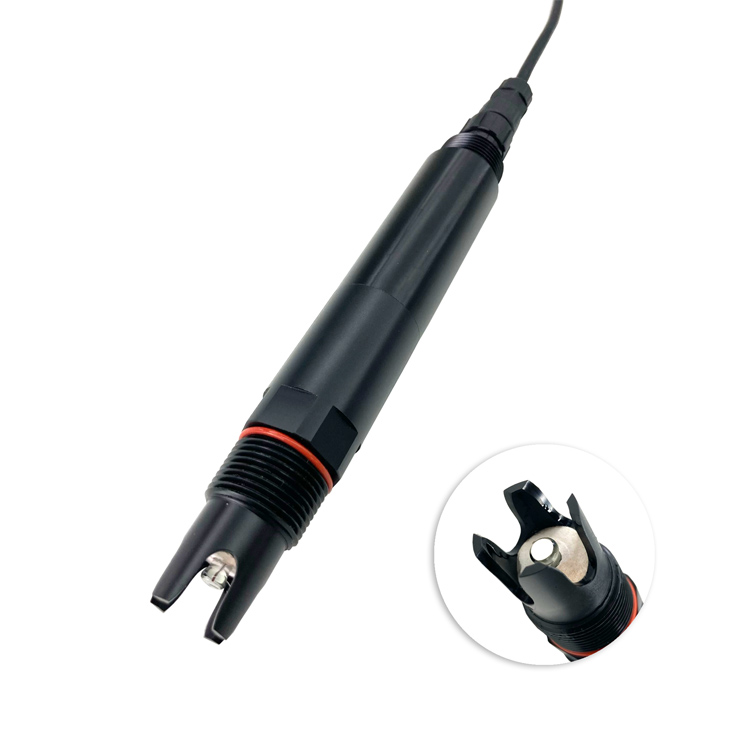
The base NBL-WQ-PH probe pictured above uses a 3/4 NPT connection and has installation-orientation requirements. A common mounting thread does not mean every probe can be clamped in the same position or laid horizontally inside a protective tube.
| Instrument | Mounting issue | Rack design check |
|---|---|---|
| Base PH / PH-4S pH probe | Horizontal or inverted installation is not permitted; specified inclination is at least 15 degrees | Support the body without obstructing the glass electrode or reference area |
| DO-4A optical probe | Keep the sensing cap immersed and clear of sediment and physical damage | Leave access for inspection and model-matched cap replacement |
| EC-S salinity probe | Specified clearance: at least 5 cm from the bottom and 2 cm from the side wall | Check clearances to rack panels as well as the tank |
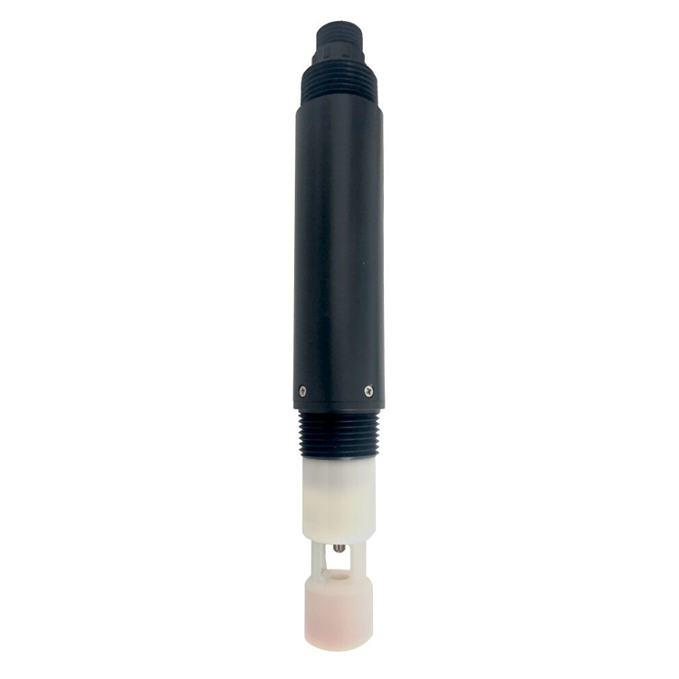
| BOD-4S optical probe | Optical path must be exposed to representative water without trapped bubbles | Allow access and clearance for the ordered cleaning arrangement |
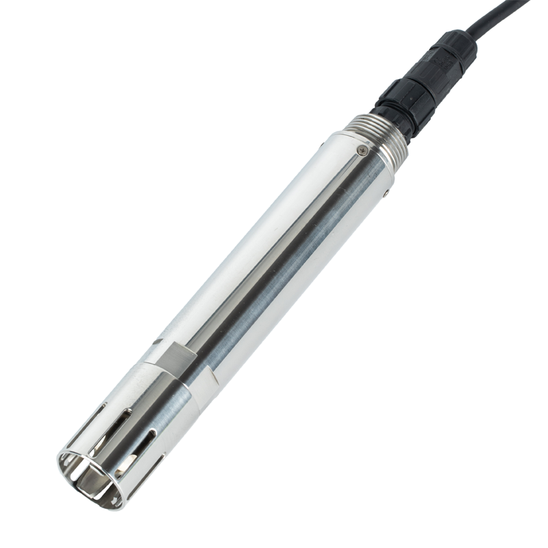
Check the mechanical drawing of each ordered probe. Holder dimensions, strain relief and thread engagement must suit the actual body. Clamping force should not be applied to the sensing cap, glass end or cable entry. The PH-4S model below is a separate pH configuration; its stainless-steel section does not remove these requirements.
Mark the lowest operating level, highest level and expected sediment accumulation on the drawing. Position each active sensing region so that it stays in the intended water during valid operation. If the water can fall below the probes, define an unavailable-data state rather than treating air exposure as an ordinary water measurement.
A fixed rack preserves a repeatable elevation but may become exposed at low water. A floating support follows the surface but changes the measurement's elevation. Select according to the monitoring objective and record which position is intended; neither arrangement automatically represents every depth in a stratified tank or pond.
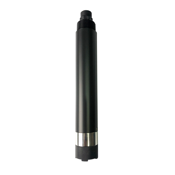
For DO, nearby aeration and local mixing remain important even with an optical probe. Protecting the DO-4A cap from impact must not create an isolated pocket of water around it. Inspect the working arrangement with the guard in place rather than accepting readings obtained only after the guard is removed.
| Model | Operating temperature / pressure | Supply / typical power |
|---|---|---|
| NBL-WQ-PH | 0-65 C; below 0.2 MPa | 12-24 VDC; 0.2 W at 12 V |
| NBL-WQ-PH-4S | 0-50 C; at or below 0.2 MPa | 12-24 VDC; 0.2 W at 12 V |
| NBL-WQ-DO-4A | 0-50 C; at or below 0.2 MPa | 12-24 VDC; 0.2 W at 12 V |
| NBL-WQ-EC-S | 0-50 C; below 0.6 MPa | 12-24 VDC; 0.2 W at 12 V |
| NBL-WQ-BOD-4S | 0-45 C; below 0.1 MPa | 12-24 VDC; 0.2 W at 12 V |
These models provide RS485 Modbus RTU, IP68 probe protection and standard 5 m cables; confirm the ordered options and cable-jacket materials. The weakest applicable instrument, holder, seal or connection limits the assembly. IP68 is not a universal installation-depth specification and does not protect an open junction box above the rack.
Route cables with enough controlled movement for retrieval, without using them as lifting lines. Keep labels readable in the service position. When several probes share a bus, map the physical holder position to the device address and PLC or logger channel before reconnecting the rack.
Only if it meets each ordered probe's dimensions, orientation and clearance requirements. The same nominal thread does not establish that a common clamp or guard leaves every sensing region unobstructed.
Not by default. Check sediment accumulation and the clearance required by each probe. A rack that meets clearance on installation day may become unsuitable after deposits build up.
It depends on the measurement objective. Floating supports follow the surface; fixed racks preserve elevation. Record the chosen reference and assess whether water-level changes alter the meaning of the data.
Use a repeatable stop or position reference, then check immersion, orientation and cable condition. Record any intentional position change so later trends are not mistaken for an unchanged monitoring point.
Demonstrate safe removal and return, probe access, required clearances, cable movement and channel identity. Confirm the valid water-level range with the completed guards and supports installed.
Send a section view with water levels, sediment allowance, support dimensions, probe list and cable route. Include the service platform or access arrangement, not only a photograph of the water surface.

An online water quality sensor rack should preserve the intended measurement position through normal operation and routine maintenance. Design the removal route, respect model-specific limits and prove that every probe can be returned correctly. This makes service practical without turning each cleaning visit into a new installation.
Prev:COD Sensor Sampling: Reject Stale Water After Pump Stops
Next:Weather Underground Station Integration: Verify the Gateway Before Ordering
Related recommendations
Sensors & Weather Stations Catalog
 Agriculture Sensors and Weather Stations Catalog-NiuBoL.pdf
Weather Stations Catalog-NiuBoL.pdf
Agriculture Sensors Catalog-NiuBoL.pdf
Water Quality Sensor Catalog-NiuBoL.pdf
Related products
 Combined air temperature and relative humidity sensor
 TDR Soil Moisture & Temperature Sensor for irrigation| RS485 |4-20mA| NBL-S-THR
 Soil pH sensor RS485 soil Testing instrument soil ph meter for agriculture |NBL-S-PH
 Wind Speed sensor Output Modbus/RS485/Analog/0-5V/4-20mA
 Tipping bucket rain gauge for weather monitoring auto rainfall sensor RS485/Outdoor/stainless steel
 Pyranometer Solar Radiation Sensor 4-20mA/RS485


Screenshot, WhatsApp to identify the QR code
WhatsApp number:+8615367865107
(Click on WhatsApp to copy and add friends)

