





— Blogs —
—Products—
 Consumer hotline +8618073152920
WhatsApp:+8615367865107
Address:Room 102, District D, Houhu Industrial Park, Yuelu District, Changsha City, Hunan Province, China
Product knowledge
Time:2026-06-03 14:11:15 Popularity:302
Quick Answer: Industrial online pH monitor installation requires a representative sample, correct electrode orientation, a suitable holder and safe access for calibration and cleaning. Keep the glass membrane and reference junction wetted, prevent trapped air, and check pressure and temperature before selecting the mounting arrangement. RS485 Modbus RTU compatibility does not compensate for a probe installed in stagnant water or a concentrated chemical stream.
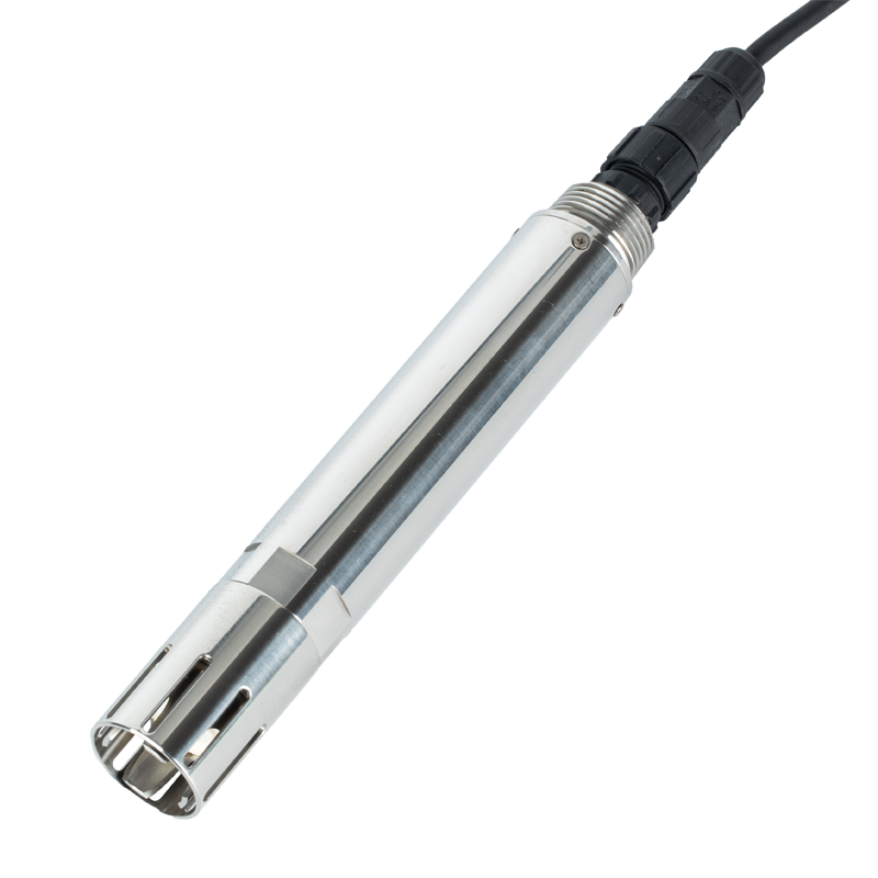
An online pH value describes the liquid at the sensing end. In a neutralization tank, the point should represent the mixed process rather than the concentrated dosing plume. Near an inlet, it may describe incoming water before mixing. At an intermittently filled outlet, the electrode may be exposed when the channel drains. These are different measurement conditions, even if all locations are physically convenient.
Identify the decision the value will support: process adjustment, trend observation, a transfer check or a separately specified discharge-monitoring function. Then inspect the actual liquid level, mixing, gas release, deposits and maintenance access through normal operating changes. A location that works at full production may be unsuitable during a low-flow shift or tank drawdown.
A pH probe does not directly measure dissolved oxygen, chlorine or general water safety. Nor does fitting it at an outlet establish regulatory approval. If the project needs an official monitoring function, define the required sampling, instrument approval and verification arrangements separately from the physical sensor installation.
| Arrangement | Suitable purpose | Installation issue to resolve |
|---|---|---|
| Immersion in a tank or basin | Observe a defined mixed-liquid point with access from a platform or bank | Maintain immersion at low liquid level, secure the holder and avoid sediment burial or strong bubble accumulation. |
| Bypass or flow-through cell | Bring a representative process stream to an accessible measurement location | Control pressure, prevent air pockets and establish what happens when sample flow stops. |
| Pipeline holder | Measure liquid within a suitable full-pipe process arrangement | Use a compatible pressure-rated assembly, acceptable orientation and an approved isolation method for removal. |
These are installation approaches, not a statement that every holder is included with the probe. The thread connection, holder, seals and process conditions must be assessed together. IP68 is an ingress classification; it is not permission to install a sensor at any process pressure or to remove it from a pressurized line.
For the NBL-WQ-PH-4S configuration described below, install the sensing end downward. Do not mount it upside down or horizontally. An inclined side installation requires at least 15 degrees from horizontal in the tip-down direction. Keep the mounting geometry consistent with the holder so that the required angle is maintained after tightening.
Both the glass membrane and the liquid junction need contact with the sample. A nominal immersion fraction alone is not enough if a protective cup traps an air pocket or the junction remains above the liquid. Inspect the actual wetted region and the lowest operating level rather than judging only how much of the body is submerged.
Provide clearance around the sensing end. Do not allow the protective structure to rest against the tank wall or pack into bottom deposits. Keep the probe out of a direct high-velocity inlet or dosing jet. Secure the assembly through its intended mounting features, not by suspending its weight from the signal cable.
The following values apply to the NiuBoL NBL-WQ-PH-4S configuration with NTC compensation and a POM/316L body. Other pH variants can have different materials, temperature elements, outputs or conductor assignments. Confirm the configuration on the purchase specification rather than combining several family versions.
| Parameter | NBL-WQ-PH-4S configuration | Installation consequence |
|---|---|---|
| Principle and range | Glass electrode; 0-14.00 pH | The measuring scale is not a declaration of suitability for every chemical mixture. |
| Accuracy and resolution | +/-0.1 pH; 0.01 pH resolution; temperature accuracy +/-0.3 degrees C | Set comparison and alarm criteria with measurement uncertainty in mind. |
| Operating temperature | 0-65 degrees C | Review the sample at the probe, including cleaning and abnormal operating conditions. |
| Operating pressure | <0.2 MPa | Check the complete assembly and pressure transients; do not substitute an IP rating. |
| Temperature compensation | Automatic, NTC | Compensates electrode response; it does not remove real chemical pH changes with temperature. |
| Supply and consumption | 12-24 VDC; 0.2 W at 12 V | Check the supply at the sensor and include the receiver's load separately. |
| Output | RS485 Modbus RTU; optional 4-20 mA | Order the required output arrangement and match it to the receiving inputs. |
| Materials and connection | POM and 316L stainless steel; 3/4 NPT thread | Verify compatibility of body, electrode, seals and holder with the actual liquid. |
| Protection | IP68 probe | Keep connectors and above-water terminations appropriately protected. |
| Cable assembly | Standard 5 m, customizable; five-core shielded twisted cable | Specify the jacket for immersion, UV and chemical exposure; shielding is not a jacket-material specification. |
| Calibration | Two-point calibration | Leave room to remove the probe safely and use fresh buffers without contaminating them. |
Do not select a pH probe as though it were a concentration transmitter whose sensitivity automatically improves with a narrower measuring span. For this configuration, the pH scale and resolution are defined. Chemical compatibility, junction behavior, sample conditions and a maintainable installation determine whether the resulting observation is usable.
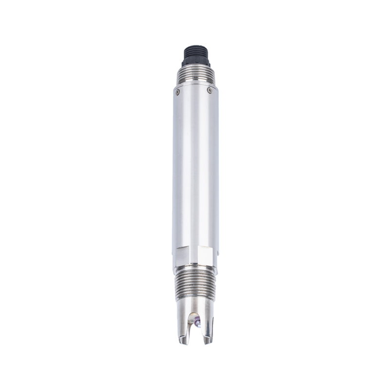
A bypass can move the measurement to a safer and more accessible position, but it introduces sample transport and conditioning. A long line, dead volume or restricted outlet can delay the sample. Gas release, cooling or exposure to air may also change the liquid before it reaches the electrode.
Locate the takeoff where it supplies the process sample needed by the application. Keep the sensing chamber filled and allow air to escape through an appropriate arrangement. Use the holder's specified flow and pressure conditions; there is no universal flow rate that suits every pH cell and sample. Confirm the sensor pressure separately from upstream pipeline pressure.
Define the stopped-flow state. A wet electrode sitting in an isolated chamber can continue reporting a plausible pH while no longer observing current process water. Where continuous sample delivery is necessary, use suitable flow confirmation or another approved indication and make an unavailable sample visible to the operator.
For the NBL-WQ-PH-4S cable configuration, red is supply positive, black is supply return, blue is RS485 A and green is RS485 B. Yellow is the optional current-output conductor and is left unconnected when that output is unused. Verify the actual assembly identification before energizing it.
The base NBL-WQ-PH version uses a different B conductor, so copying a wiring pattern between similar-looking probes can create a communication fault. For an analog option, confirm its wiring and receiving-input requirements rather than assuming that the RS485 terminals carry a current-loop signal.
Route the cable with mechanical support and protect joints against water ingress. Keep it separated from motor and variable-frequency-drive power wiring according to the installation design. Use the plant's grounding and shielding arrangement; do not disconnect protective earth or improvise a new grounding path simply to suppress a noisy reading.
Where an interference investigation indicates a need for isolation, select a suitable engineered solution for the power or communication path. A valid checksum only confirms a received digital frame; it cannot prove that electrical conditions at the electrode are suitable for the chemical measurement.
A successful buffer calibration followed by an unstable process reading is a reason to inspect the installation, sample and interference. It is not a reason to keep changing calibration until the displayed process number matches an expectation. Likewise, a remote value that differs by a fixed scale factor should be checked through the data path before altering the electrode.
Leave space for a technician to remove and support the sensor without damaging the glass or straining the cable. Where a pipe or pressurized cell is involved, use the approved isolation, depressurization and access procedure. A thread connection alone does not make a probe safely retractable during operation.
For the stated configuration, keep the electrode wet in the specified 3.5 mol/L potassium chloride storage solution when removed from service. Short rinsing with deionized water is different from long-term storage in it. Do not leave the electrode dry while the installation is waiting for its next commissioning stage.
Set the inspection routine around observed deposits and process changes. The holder should allow cleaning and recalibration without creating a different measurement point on each visit. Keep the initial mounting position and reference comparison available so later changes can be distinguished from instrument drift.
For a NiuBoL installation review, provide the liquid composition, operating and abnormal temperature/pressure, tank or pipe geometry, expected level variation and receiving interface. Photographs of the proposed sensing point and removal route help determine the holder and cable arrangement. This is more useful than selecting only by a pH range and enclosure rating.
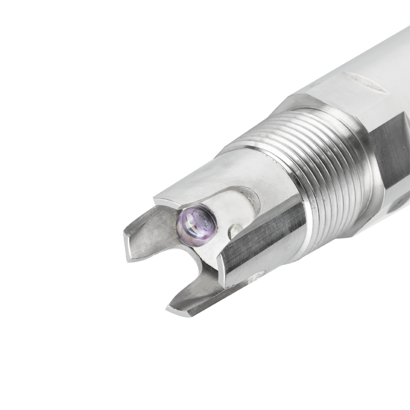
The NBL-WQ-PH-4S configuration described here must not be horizontal or upside down. Use a tip-down orientation; an inclined side installation needs at least 15 degrees from horizontal. Confirm the holder maintains that orientation.
Keep both the glass membrane and reference junction wetted throughout the intended measurement period. Check the sensing-end geometry and lowest liquid level; an approximate body fraction does not address trapped air or an exposed junction.
No. This configuration has a separate operating-pressure limit below 0.2 MPa. The holder, seals and process connection also need suitable ratings, including the actual temperature and pressure transients.
It can display the pH of retained liquid while no longer representing current process water. If continuous delivery is required, provide an appropriate stopped-flow indication and define how that condition affects alarms or control.
Check bubble contact, incomplete mixing and the local dosing plume. Also investigate grounding or electrical interference where relevant. A stable buffer reading does not establish that the chosen process location is representative.
No. The stated 4S configuration uses blue A and green B; the base configuration has a different B conductor. Verify the delivered wiring identification and optional-output arrangement before connection.
Verify calibration, installed sample representativeness, receiver scaling and fault behavior. Any dosing function also needs its own mixing, maximum-addition and equipment safeguards; pH communication alone does not validate that control design.
Industrial online pH monitor installation succeeds when the probe observes the intended liquid and remains safely serviceable. Confirm orientation, wetting, pressure, sample delivery and the complete signal path for the ordered configuration. A correct holder and a representative sample are as important as the NiuBoL sensor's measurement and communication specifications.
Prev:pH Meter Working Principle: Glass Membrane, Reference and Digital Output
Next:Online pH Meter Troubleshooting: Buffers Pass but Process Readings Differ
Related recommendations
Sensors & Weather Stations Catalog
 Agriculture Sensors and Weather Stations Catalog-NiuBoL.pdf
Weather Stations Catalog-NiuBoL.pdf
Agriculture Sensors Catalog-NiuBoL.pdf
Water Quality Sensor Catalog-NiuBoL.pdf
Related products
 Combined air temperature and relative humidity sensor
 TDR Soil Moisture & Temperature Sensor for irrigation| RS485 |4-20mA| NBL-S-THR
 Soil pH sensor RS485 soil Testing instrument soil ph meter for agriculture |NBL-S-PH
 Wind Speed sensor Output Modbus/RS485/Analog/0-5V/4-20mA
 Tipping bucket rain gauge for weather monitoring auto rainfall sensor RS485/Outdoor/stainless steel
 Pyranometer Solar Radiation Sensor 4-20mA/RS485


Screenshot, WhatsApp to identify the QR code
WhatsApp number:+8615367865107
(Click on WhatsApp to copy and add friends)

