





— Blogs —
—Products—
 Consumer hotline +8618073152920
WhatsApp:+8615367865107
Address:Room 102, District D, Houhu Industrial Park, Yuelu District, Changsha City, Hunan Province, China
Product knowledge
Time:2026-06-06 09:36:38 Popularity:342
Quick answer: Industrial pH electrode maintenance should distinguish contamination, calibration drift, electrode failure and receiving-system errors. Check the electrode in suitable fresh buffers before and after approved cleaning. Restore the measurement only after verification, and keep the dosing or control system in its approved maintenance state while the probe is removed.
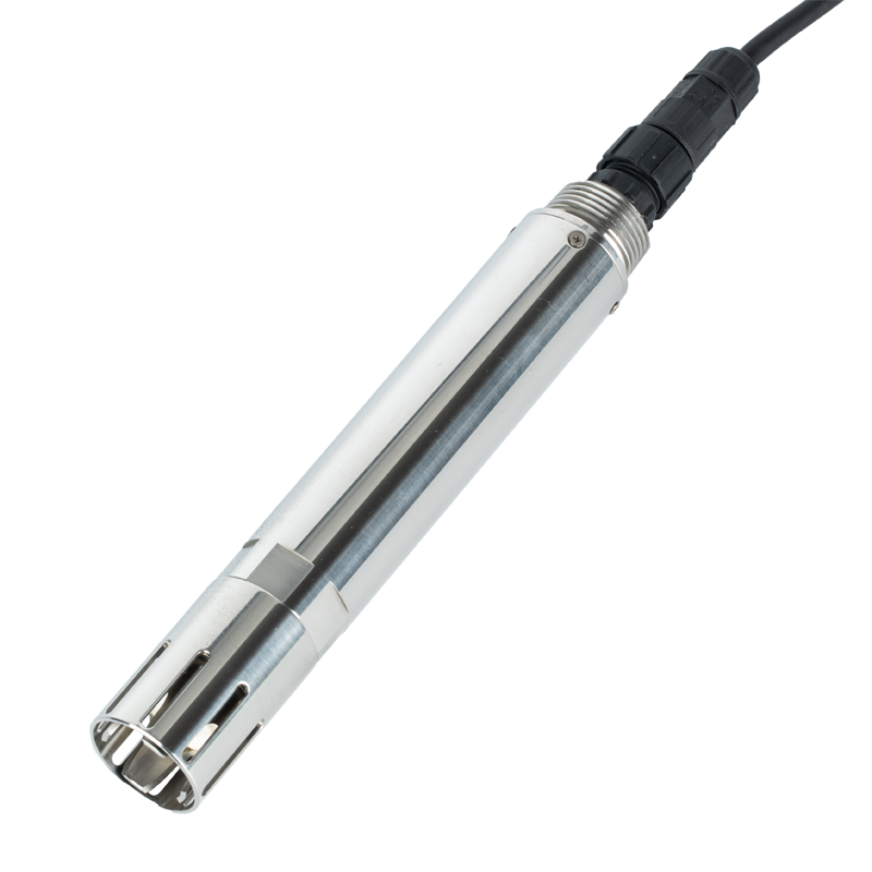
An industrial pH reading depends on the glass response, reference system and the sample around the electrode. Deposits, a restricted junction or a dehydrated electrode can cause slow response or drift. Record a check in a suitable buffer before cleaning and again afterwards; this helps distinguish contamination from a calibration or electrode-life issue.
Use the cleaning and storage procedure for the specific electrode. The process temperature, pressure and chemistry must also suit its materials. Calibration cannot compensate for an unsuitable installation, persistent air exposure or a chemically incompatible reference system.
Begin with the observed symptom and its timing. A slow response after weeks in a fouling liquid suggests a different investigation from a sudden discrepancy after a PLC configuration change. If a probe checks correctly in buffers but behaves poorly in the process, examine the sample location, wetting, mixing and operating conditions. Repeatedly changing calibration to match an unexplained process reading can hide the original fault.
| Observed behavior | Distinguishing check | Reason to delay adjustment |
|---|---|---|
| Slow stabilization in fresh buffers | Inspect hydration, deposits, temperature equilibration and reference junction condition. | A new offset does not restore a fouled or damaged sensing surface. |
| Good buffer response, poor process agreement | Check representative sampling, air contact, bubbles and process conditions. | The two instruments may not be observing equivalent samples. |
| Local reading correct, PLC value wrong | Trace register decoding or analog scaling through the receiving system. | Physical electrode calibration cannot repair a software mapping error. |
| Different readings after each immersion | Check buffers, rinsing, stable immersion and connections before judging the electrode. | Contamination or an intermittent connection may make a calibration unreliable. |
Identify which alarms and control actions use the pH point. Follow the site's approved maintenance procedure before removing the sensor, and make its unavailable status visible. Do not let a probe placed in a calibration buffer continue to drive a dosing decision as though it were still in the tank. Restore automatic operation only after the installed measurement and the receiving channel have been checked.
For a pipe installation, isolate and depressurize using the designed arrangement before removal. Do not assume a threaded probe is retractable under pressure. Inspect access, strain relief and the ability to keep the cable connection dry during service. A connector or splice wet with process liquid needs investigation; resealing it without checking the electrical condition can leave an intermittent fault.
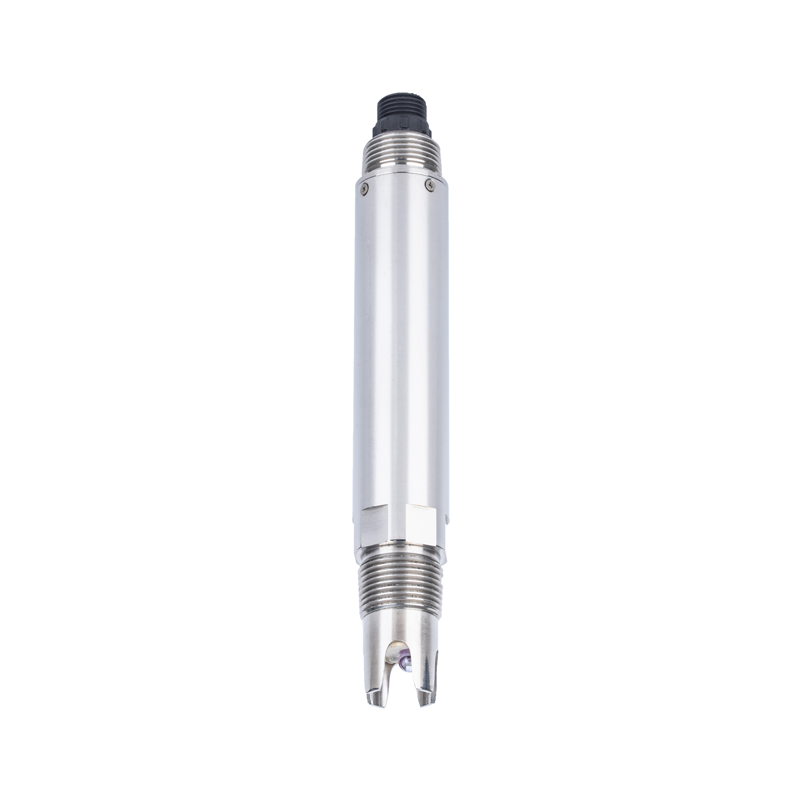
Rinse contamination from the electrode using the procedure appropriate to its construction. Avoid scraping the glass or applying an abrasive treatment simply because a deposit is visible. Choose any chemical cleaner for the actual foulant, electrode and wetted materials, with its specified concentration, contact time and rinsing. A general reference to acid cleaning is not a universal recipe for every industrial pH probe.
Inspect the sensing end and reference junction for damage and persistent deposits. Keep the terminal and connector clean and dry. If the electrode has dried, use the approved conditioning procedure before testing its response; immediately calibrating a dehydrated probe may produce a correction that does not remain valid after it rehydrates. Do not dismantle a sealed assembly or refill it unless the selected electrode is designed for that service.
After cleaning, check fresh buffer portions again before changing settings. Record the difference from the pre-cleaning check and allow temperature and response to settle. Cleaning may restore an acceptable measurement without recalibration. When adjustment is required, the saved calibration should describe a stable electrode, not compensate for remaining dirt or a moving reading.
Choose the calibration points supported by the delivered transmitter and electrode configuration. Nominal pH 6.86 and 7.00 buffers are not interchangeable when the instrument expects a particular family. The same applies to alkaline buffer values such as 9.18 and 10.01. Check the buffer's temperature-dependent value rather than assuming that its nominal label applies at every calibration temperature.
Use clean vessels and fresh portions, rinse between solutions and avoid returning used buffer to the stock bottle. Select suitable points around the working region when the supported calibration procedure allows it. Keep the buffer identity, temperature, stable readings and any adjustment in the service record. An independent check after adjustment is more useful than recording only that the calibration command completed.
Automatic temperature compensation does not convert every sample's actual pH to one common chemical state. The solution itself can change pH as temperature or gas exchange changes. For a process comparison, record temperature and handle the sample consistently. A cooled sample carried to a laboratory may not be equivalent to the liquid surrounding the installed electrode.
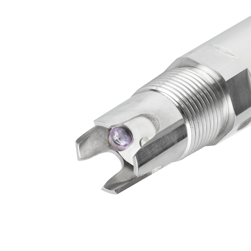
These NiuBoL specifications describe an NBL-WQ-PH-4S configuration with NTC temperature compensation. Other pH assemblies can have different temperature elements, materials or operating limits. Confirm the delivered configuration when replacing a probe rather than identifying it solely by the appearance of its stainless housing or the thread size.
| Parameter | NBL-WQ-PH-4S configuration | Maintenance implication |
|---|---|---|
| Range / resolution | 0-14.00 pH / 0.01 pH | A display digit is not a detection limit or an accuracy guarantee. |
| Accuracy | +/-0.1 pH; temperature +/-0.3 degrees C | Agree verification limits with the reference and test conditions in mind. |
| Liquid temperature / pressure | 0-65 degrees C; pressure <0.2 MPa | Match this specific version to the process, including cleaning and pressure excursions. |
| Supply / consumption | 12-24 V DC; 0.2 W at 12 V | Check supply at the operating probe before diagnosing a communication fault. |
| Output | RS485 / Modbus RTU; 4-20 mA optional | Order the required output and verify the receiver after replacement. |
| Temperature compensation | Automatic, NTC configuration | Do not substitute a different temperature element without compatibility confirmation. |
| Housing / fitting / protection | POM and 316L stainless steel; 3/4 NPT; IP68 | Material and thread compatibility require checks beyond the ingress rating. |
| Cable | 5 m standard; five-core shielded twisted-pair arrangement | Confirm wire functions and jacket compatibility for the ordered assembly. |
| Calibration | Two-point calibration | Use the supported buffer set and verify the result before returning to control. |
For the PH and PH-4S versions described here, storage uses 3.5 mol/L potassium chloride solution in a suitable protective sleeve or container. A brief rinse with deionized water is different from long-term storage in it. Do not leave the glass sensing end dry or assume that a generic 3 mol/L instruction for another electrode is the specified solution for this assembly. Keep the storage arrangement clean and inspect it before returning a spare to use.
A spare electrode is useful only if it matches the transmitter or includes the required electronics. Distinguish a sensing electrode from a complete digital transmitting probe in the quotation. Confirm output, temperature compensation, materials, fitting and cable termination. Do not assume that a replaceable glass element, internal reference assembly and complete sealed sensor have the same replacement procedure.
Check device address, serial settings, selected measurement registers and the receiving application's scaling. A replacement with a default address may conflict with an existing instrument. Keep pH and temperature as separate named values, and verify that the timestamp advances after the sensor returns. A plausible retained value can conceal a device that has not resumed communication.
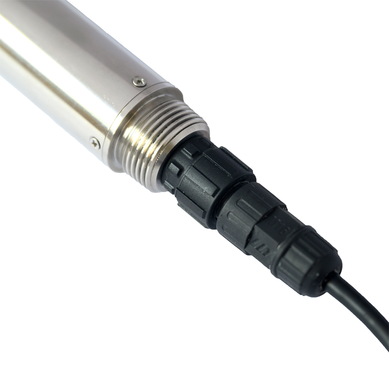
Do not apply one wire-color convention across models. For the NBL-WQ-PH base version, the listed RS485 pair is blue A and white B; for the PH-4S five-core arrangement it is blue A and green B, with yellow used for the optional current output. Confirm the supplied cable definition before connecting. Conductor construction or waterproofing does not establish chemical compatibility of every extension cable.
For a current-output installation, compare the configured transmitter span with the PLC input conversion and any HMI scaling. Test the receiving path under the input module's approved procedure when required. That electrical test does not calibrate the electrode. Conversely, a good electrode buffer check does not prove that the PLC or remote application displays the same engineering value.
Use fouling and verified drift to determine how often the site needs inspection. Wastewater deposits, a lightly contaminated process stream and a periodically drained tank can require different attention. Record the reason for service and the change after it, not only the date. Shorten an interval when the record shows deterioration; avoid promising the same cleaning period or electrode life for every liquid.
Replacement is justified when correct conditioning, cleaning and calibration cannot produce a stable verified result within the agreed criteria, or when physical damage or material incompatibility makes further use inappropriate. Include buffer results, process chemistry, temperature, pressure and response symptoms in a NiuBoL replacement inquiry. This helps distinguish a consumable electrode issue from an installation or receiving-system problem.
No. Check fresh buffers, temperature, hydration and contamination first. Record results before and after approved cleaning. Adjustment should follow diagnosis; it must not conceal an unstable electrode or an unsuitable sample point.
Not as the long-term storage method for these PH and PH-4S versions. Use their specified 3.5 mol/L KCl arrangement. Rinsing briefly with deionized water is a different operation from prolonged storage.
Only if the transmitter's supported procedure correctly recognizes and uses the selected set. Do not substitute nominal values in a fixed buffer sequence. Use the buffer's value at the actual temperature and verify after calibration.
No. It handles the instrument's defined temperature response, not every temperature-dependent change in solution chemistry. Compare readings under controlled, recorded sample conditions and confirm the actual temperature element used by the assembly.
Check register selection, data interpretation, analog span and duplicate scaling through the receiving path. Also confirm data age. Do not alter the electrode's calibration to make a correctly measured pH fit an incorrectly configured tag.
No universal cleaner follows from the pH measurement principle. Match the deposit, glass, reference system and housing to the approved procedure. Avoid arbitrary concentrations, prolonged soaking or abrasive cleaning that can damage the assembly.
Identify whether an electrode or full transmitting probe is required. Include model, output, compensation element, process limits, materials, fitting and cable. Attach service observations so NiuBoL can review compatibility without assuming that similar-looking probes are interchangeable.
Industrial pH maintenance should address the electrode, sample point and receiving system separately. Use model-specific buffers and storage instructions, record changes during service and verify the displayed channel after work. Those records make a replacement request more precise.
Prev:Domestic Water Quality Parameters After Tank Storage: What to Compare
Next:Online DO Meter Remote Monitoring: Sample Time, Data Gaps and Local Control
Related recommendations
Sensors & Weather Stations Catalog
 Agriculture Sensors and Weather Stations Catalog-NiuBoL.pdf
Weather Stations Catalog-NiuBoL.pdf
Agriculture Sensors Catalog-NiuBoL.pdf
Water Quality Sensor Catalog-NiuBoL.pdf
Related products
 Combined air temperature and relative humidity sensor
 TDR Soil Moisture & Temperature Sensor for irrigation| RS485 |4-20mA| NBL-S-THR
 Soil pH sensor RS485 soil Testing instrument soil ph meter for agriculture |NBL-S-PH
 Wind Speed sensor Output Modbus/RS485/Analog/0-5V/4-20mA
 Tipping bucket rain gauge for weather monitoring auto rainfall sensor RS485/Outdoor/stainless steel
 Pyranometer Solar Radiation Sensor 4-20mA/RS485


Screenshot, WhatsApp to identify the QR code
WhatsApp number:+8615367865107
(Click on WhatsApp to copy and add friends)

