

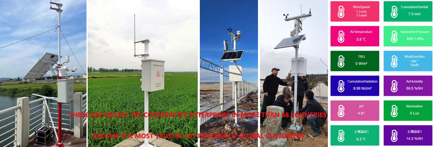
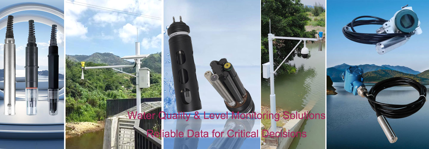
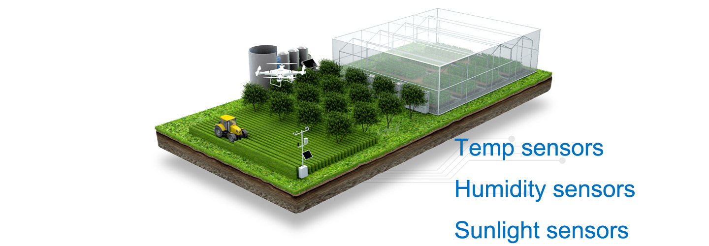

An outdoor temperature transmitter converts an air-temperature measurement into a signal that a PLC or logger can interpret. For a confirmed −40–80°C range mapped to 4–20 mA, subtract the live zero, divide by the current span, multiply by the temperature span, then restore the lower temperature endpoint. Verify both endpoints before accepting readings.
What does the outdoor transmitter send to the PLC?
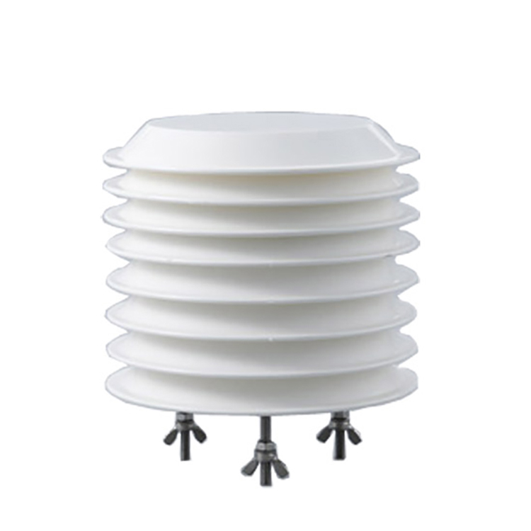
Ambient Temperature Transmitter with 4-20mA Output
The sensing element and the receiving channel have different jobs. The element responds to its local thermal environment; the output circuit represents that response electrically. The PLC then assigns engineering units to the received signal. A credible temperature on a dashboard does not demonstrate that these stages agree. An incorrect range can still produce a smooth daily curve.
The NiuBoL ambient temperature transmitter has a published temperature range of −40–80°C, accuracy of ±0.5°C and resolution of 0.1°C. The listed supply option is 12–24 V DC, with RS485 or 4–20 mA output configurations. Confirm the ordered temperature channel and its endpoint mapping; available options do not establish the wiring or scale of every delivered unit.
Keep other measured quantities separate. A combined atmospheric instrument can have several channels, but a single analog current cannot identify its own parameter. Label the cable, receiving terminal and software tag with the same quantity. Otherwise, a correctly decoded number can be attached to the wrong unit without producing an obvious electrical fault.
Convert 4–20 mA into temperature with both endpoints
Use T = L + ((I − 4) / 16) × (U − L), where I is current in mA, L is the lower endpoint and U the upper endpoint in °C. For L = −40°C and U = 80°C, the temperature span is 120°C. The conversion therefore has a slope of 7.5°C per mA, not 5°C per mA.
The following bench values are an illustrative calculation based on assumed site values, not a measured field record. They assume the supplied analog version uses exactly this mapping. They are electrical test targets, not observations of air temperature. Disconnect the field output before connecting a simulator, and select its operating mode to suit the receiving circuit.
| Applied current, mA | Expected temperature, °C | Test condition |
|---|---|---|
| 4.0 | −40 | Assumed lower endpoint |
| 5.6 | −28 | Isolated input simulation |
| 7.2 | −16 | Isolated input simulation |
| 8.8 | −4 | Isolated input simulation |
| 10.4 | 8 | Isolated input simulation |
| 12.0 | 20 | Midspan input simulation |
| 13.6 | 32 | Isolated input simulation |
| 15.2 | 44 | Isolated input simulation |
| 16.8 | 56 | Isolated input simulation |
| 18.4 | 68 | Isolated input simulation |
| 20.0 | 80 | Assumed upper endpoint |
At an assumed 13.6 mA input, the normalized fraction is (13.6 − 4) / 16 = 0.60. Multiplying 0.60 by 120°C and adding −40°C gives 32°C. The inverse check is I = 4 + ((32 + 40) / 120) × 16 = 13.6 mA. Save both directions beside the channel configuration.
Equal current steps should produce equal temperature steps while the mapping remains linear. Each 1.6 mA step in the table corresponds to 12°C. If the receiving display follows a different increment, inspect software scaling before adjusting the field instrument. Nonlinearity, clipping and a fixed displacement call for different tests; one corrected midpoint cannot distinguish them.
Why can a plausible reading still be wrong?
Suppose the receiver retains a default 0–100°C scale while the connected output represents −40–80°C. At the same assumed 13.6 mA, that default produces 60°C instead of 32°C: a +28°C difference. This is an illustrative calculation based on assumed site values, not a measured field record. Trimming the transmitter to hide this mismatch would corrupt an otherwise correct measurement.
The endpoint pattern identifies the problem. At 4 mA, the incorrect display shows 0°C instead of −40°C, a +40°C difference. At 20 mA, it shows 100°C instead of 80°C, a +20°C difference. Because the discrepancy changes across the span, subtracting a constant 28°C cannot repair the whole range. Correct the endpoint configuration instead.
Check whether the input module already reports milliamps or returns raw counts. Applying a second current conversion to an already scaled value creates another error. Obtain the receiver's actual count endpoints rather than borrowing a familiar count range from another PLC. The count convention belongs to the input module, not to the temperature probe.
Separate the PLC display from the historian calculation as well. A correct local reading can become wrong when an export applies an old formula. Record the injected current, receiver value and archived value together. Preserve the configuration revision with these records so a later replacement does not silently reinstate an obsolete range.
Translate receiving error into degrees before setting tolerances
Electrical uncertainty becomes a temperature uncertainty through the slope. For an assumed receiving-chain error bound of ±0.08 mA, multiplication by 7.5°C per mA gives ±0.60°C. This is an illustrative calculation based on assumed site values, not a measured field record. The bound is not a NiuBoL specification; replace it with the actual module's documented error.
If the published ±0.5°C sensor accuracy applies under the conditions being assessed, adding it to the assumed ±0.60°C electrical bound gives a conservative ±1.10°C bound. This addition is not a statistical confidence interval. It also excludes exposure bias, reference uncertainty and drift. Do not promise installed accuracy from a partial budget.
Likewise, 0.1°C reported resolution does not establish ±0.1°C accuracy. With this mapping, a 0.1°C increment corresponds mathematically to about 0.0133 mA. That conversion does not prove that every analog output or receiving input can resolve the increment. Verify analog-output specifications separately from the sensing element's digital reporting resolution.
Agree separate electrical and thermal acceptance checks. An electrical check asks whether an applied current becomes the intended temperature. A thermal comparison asks whether the installed sensing arrangement represents the intended air. Combining the two into one unexplained tolerance makes troubleshooting harder and can hide a failing input behind an apparently acceptable overall difference.
Outdoor exposure errors that signal scaling cannot repair
A probe warmed by direct sunlight can report a real temperature at its own element while failing to represent ambient air. Nearby metalwork, exhaust outlets and stagnant spaces can create similar bias. Specify the exposure and suitable radiation protection for the measurement purpose. Do not compensate for a changing solar influence with a permanent PLC offset.
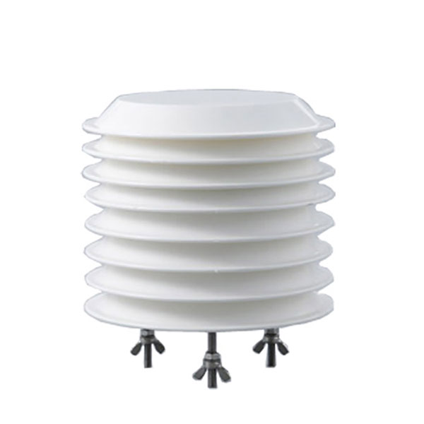
The outdoor temperature and humidity version is another configuration to assess against the installation. Check the delivered assembly, output choice and environmental conditions before replacing an existing channel. A housing description is not evidence that unrestricted placement beside a hot surface gives representative air temperature.
Moisture at outdoor connectors may cause intermittent failures rather than a steady offset. Inspect glands, cable support and drainage without sealing the sensing region inside an unsuitable enclosure. A current that remains believable during a wet connector fault can be more misleading than a clear loss of signal. Correlate unusual readings with weather and service activity.
Current outside the configured measurement span needs an explicit handling rule. Do not assume a particular diagnostic current or fault convention unless the supplied unit defines it. A disconnected circuit must not become a valid low-temperature observation, and a held previous value must not receive the same quality flag as a new reading.
Commission the signal path without disguising a sensor fault
Begin with a configuration record: quantity, units, endpoint mapping, output variant, receiving module and terminal identification. Record the permissible supply and loading conditions from the delivered instructions. A 4–20 mA label alone does not tell you whether an output is loop-powered or separately powered, nor whether the input provides excitation.
With the process channel safely isolated, test the receiver using an appropriate current simulator. Verify the lower endpoint, midpoint and upper endpoint, then use intermediate points if the discrepancy suggests clipping or an unexpected transfer function. Record readings before making changes. Test source and simulation modes deliberately; connecting incompatible powered circuits can damage equipment.
Reconnect the transmitter and check its signal under a sufficiently steady air condition. Use a suitable independent reference with comparable exposure and allow both instruments to settle. Record weather, protection and mounting differences. A simulator pass cannot establish thermal calibration because the simulation bypasses the element that actually measures air temperature.
A compatible NBL-PH-1 data logger can provide acquisition and storage within a specified system. Confirm the configured input supports the selected output, rather than assuming a logger name establishes channel compatibility. Preserve acquisition time and quality information when transferring values to a remote platform.
Finally, deliberately interrupt the measurement input using the permitted procedure and observe the complete chain. Confirm that missing data stays invalid through display, archive and any external alarm logic. Restore the connection and inspect recovery. This test checks behavior the scaling equation cannot describe, including stale values and unexpected automatic substitutions.
Temperature signal questions from outdoor installations
Does 4 mA mean the air temperature is zero degrees?
No. It represents the configured lower measurement endpoint. In the assumed mapping used here, 4 mA corresponds to −40°C, while 0°C would require about 9.33 mA. Read the supplied endpoint definition and verify the PLC calculation. Do not substitute a different temperature range merely because the input current looks normal.
Can I correct every temperature reading with one offset?
Only after identifying a genuinely constant difference and following the approved adjustment procedure. The wrong-range example has different endpoint errors, so one offset cannot repair it. Compare several injected currents first. If electrical conversion passes, investigate exposure and reference conditions before changing the physical measurement or introducing a permanent software correction.
Does a current simulator calibrate the outdoor sensing element?
No. It verifies the receiving electrical path, including conversion and display, without testing how the element measures air. A separate thermal comparison needs a suitable reference, comparable exposure and adequate settling. Keep the simulator record and thermal comparison record distinct; success in one does not establish success in the other.
Can an RS485 unit replace the analog transmitter directly?
Not at an unchanged current-input terminal. RS485 requires a compatible communication interface and the delivered protocol definition. Check power connections, address settings and interpretation for that particular version. Output alternatives should be selected during configuration, not treated as interchangeable cable functions. Recheck the entire receiving path after a change of interface.
What should happen when the current leaves the measurement span?
The receiving application should flag the observation for the defined fault or over-range handling, rather than silently treating it as valid ambient temperature. Ask for the actual unit's diagnostic behavior. A generic current convention does not establish its implementation. Test a permitted disconnect and recovery sequence before trusting unattended records.
Which records help resolve a mismatch after installation?
Provide the endpoint mapping, measured current, local receiver reading, archived value and their timestamps. Include instrument identity, input-module configuration and recent changes. Add photographs of exposure and cable joints if the electrical checks pass. These records separate a conversion mistake from mounting bias, intermittent connections or a genuine need for sensor inspection.
Accept the conversion, then accept the air measurement
An outdoor transmitter needs a verified scale and a representative sensing location. For the confirmed −40–80°C mapping, 13.6 mA converts to 32°C; another PLC range changes that answer. Accept the electrical path with documented input tests, then assess thermal performance separately. Retain fault behavior and configuration history alongside the normal data.
Send the required temperature range, output version, receiving-input details and proposed mounting arrangement through the project contact form. Include any mismatch as current and temperature pairs, rather than only a screenshot of the final dashboard.