


A sprinkler irrigation controller must match the valve coil's voltage, current and switching method before its outputs are connected. Check continuous load, starting demand, relay contact duty and voltage at the distant valve. A relay contact usually switches a separate supply; a sensor port or communications terminal cannot substitute for a valve driver.
Identify the valve circuit before selecting a controller
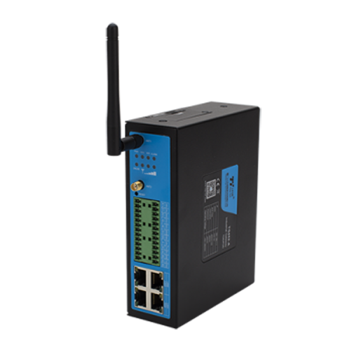
Smart Data Collector for a separately specified irrigation control panel; relay duty requires confirmation
Begin with the actuator label, not the number of watering programs on a display. Record whether the valve requires AC, continuously energized DC, a reversing motor supply or a brief latching pulse. Those loads need different output arrangements. A terminal marked relay does not by itself identify any of these operating methods.
Keep controller supply voltage separate from switched voltage. A unit powered from 24 VDC might provide isolated contacts, powered transistor outputs or a mixture of interfaces. Its supply rating does not establish what a contact can interrupt. Check terminal identification and the approved wiring diagram before deciding that two products are electrically compatible.
NiuBoL's Smart Data Collector provides acquisition and relay-control interfaces for an engineered panel. Its listed arrangement includes 2 relay interfaces and 2 digital inputs. Those interface counts are not a contact-current rating or a complete sprinkler irrigation controller specification. Obtain the selected unit's load ratings and implement the required control functions separately.
Two relay interfaces also do not directly provide six independent valve circuits. Expansion hardware or another architecture would be required for that assignment. Do not assume an RS485 connector adds switched channels: it carries communication, not solenoid power. A networked output module needs its own verified electrical ratings, supply and behavior when communications fail.
Build a current budget for the sprinkler irrigation controller
This is an illustrative calculation based on assumed site values, not a measured field record. The example uses continuously energized 24 VDC coils and invented design inputs for sizing practice only. None of the listed currents is a NiuBoL model rating. The assumed operating rule permits at most two zone valves simultaneously.
| Circuit | Assumed running current, A | Assumed 24 VDC power, W | Budget condition |
|---|---|---|---|
| Zone valve V1 | 0.18 | 4.32 | One permitted zone load |
| Zone valve V2 | 0.22 | 5.28 | One permitted zone load |
| Zone valve V3 | 0.26 | 6.24 | Second-largest zone load |
| Zone valve V4 | 0.30 | 7.20 | Largest zone load |
| Zone valve V5 | 0.24 | 5.76 | One permitted zone load |
| Zone valve V6 | 0.20 | 4.80 | One permitted zone load |
| Master valve | 0.28 | 6.72 | Present during watering |
| Pump interface coil | 0.06 | 1.44 | Command circuit only |
| Controller electronics | 0.14 | 3.36 | Assumed panel component |
| Sensor supply group | 0.10 | 2.40 | Combined assumed load |
Using P = V × I, valve V4 consumes an assumed 24 × 0.30 = 7.20 W while held open. That calculation does not establish its pull-in demand or the required relay category. Obtain coil data at the relevant supply conditions; do not calculate an inductive starting current from a running power label alone.
The worst permitted running combination is V4 plus V3, master valve, pump interface, electronics and sensors. Its sum is 0.30 + 0.26 + 0.28 + 0.06 + 0.14 + 0.10 = 1.14 A, or 27.36 W at 24 VDC. Record the simultaneity assumption with the supply selection rather than hiding it in a spreadsheet.
Applying an assumed planning multiplier of 1.25 gives 1.425 A and 34.20 W. That multiplier is not a prescribed design margin. Verify actual supply derating and transient capability. If the chosen hardware cannot enforce the two-valve restriction, the current budget is invalid and must include the combinations that can really occur.
For comparison, energizing all six assumed zone coils with the other listed loads gives 1.98 A, or 47.52 W. A mistaken test command could therefore exceed the restricted running budget. Confirm what commissioning mode, local switches and expansion modules can energize. Software intentions do not change the current flowing through a shared return conductor.
Which relay rating applies to a solenoid valve?
A resistive contact rating is not permission to switch an inductive coil at the same current. Closing and opening place different demands on the contact. Ask for the applicable AC or DC inductive rating, permitted switching voltage, duty cycle and expected electrical endurance. Do not infer these from the relay enclosure size or output count.
Assume V4 requires 0.72 A during pull-in and V3 requires 0.62 A, with all other example currents unchanged. Simultaneous starting then draws 1.92 A, or 46.08 W at 24 VDC. A supply selected only from the 1.425 A planning figure may fail this starting condition. Its overload curve and permitted transient duration decide compatibility.
Staggering valve starts might reduce coincident demand, but it does not increase an individual relay's current rating. Check each channel, any common terminal and the shared supply independently. An interposing relay can separate duties when correctly specified; it also adds a coil load and another component whose de-energized condition must be understood.
Coil suppression requires the actuator and switching-device instructions. A diode may be suitable for a compatible DC circuit, but it is not a universal accessory for AC or polarity-reversing latching outputs. Suppression can change release behavior. Have the panel designer confirm polarity, placement and resulting operation instead of attaching an arbitrary component across every valve.
Calculate voltage at the end of the valve cable
Use round-trip conductor resistance, not only the outward length. For a separate copper pair, R = 2ρL / A, where L is one-way length and A is conductor cross-section. The following table assumes 85 m one-way length, copper resistivity of 0.0175 Ω·mm²/m at the calculation reference condition, and a 0.30 A holding load.
| Wiring assumption | Calculated value | Meaning |
|---|---|---|
| Separate pair, 1.0 mm² | 2.975 Ω | Round-trip resistance |
| Separate pair, 1.0 mm² | 0.8925 V | Holding-current drop |
| Separate pair, 1.0 mm² | 23.1075 V | Valve voltage from 24 V source |
| Separate pair, 0.5 mm² | 5.950 Ω | Round-trip resistance |
| Separate pair, 0.5 mm² | 1.785 V | Holding-current drop |
| Separate pair, 0.5 mm² | 22.215 V | Valve voltage from 24 V source |
| Smaller pair, source at 21.8 V | 20.015 V | Valve voltage before joint losses |
For the 1.0 mm² pair, resistance is 2 × 0.0175 × 85 / 1.0 = 2.975 Ω. Multiplying by 0.30 A gives 0.8925 V loss. This holds the assumed current at 0.30 A for a voltage-drop estimate; it is not a coil impedance model, pull-in calculation or cable approval. Higher conductor temperature, joints and a different route can increase actual resistance.
Suppose the example coil requires at least 21.6 V during holding. The smaller pair leaves 22.215 − 21.6 = 0.615 V margin at a 24 V source, before joint losses. At a source reduced to 21.8 V, the calculated 20.015 V is below that assumed requirement. Measure supply under load, not just with outputs disconnected.
A shared common wire carries the sum of simultaneously energized branch currents. The separate-pair table cannot be applied unchanged to that topology. Calculate every common segment using its actual length and combined current. A sprinkler irrigation controller can have correctly selected individual outputs and still fail to open distant valves because the common path was undersized.
Keep sensor inputs separate from valve and pump power
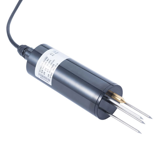
The NiuBoL NBL-S-THR irrigation soil sensor offers ordered RS485 Modbus RTU, current or voltage signal options. Its supply is 12–24 VDC, with approximately 0.3 W consumption. That is a measurement-device supply requirement, not a source of valve power. Match the selected output to the receiving input rather than treating every cable as interchangeable.
For its current-output option, the receiving load must not exceed 250 Ω. At 20 mA, a 250 Ω load develops 5 V by Ohm's law. This input calculation does not turn an analog terminal into a switched 5 V supply. Check loop wiring, input configuration and the complete voltage budget for the ordered arrangement.
NiuBoL's RTU data collector is another acquisition-and-control component to evaluate against the actual interface schedule. It does not remove the need for a separately designed motor circuit. A sprinkler irrigation controller should command the appropriate pump starter or drive interface; it must not carry motor power through an unverified signal output.
Keep noisy switching conductors away from low-level measurement wiring as required by the equipment installation instructions. Label protective earth, DC common, sensor reference and communication conductors distinctly. They are not interchangeable merely because a meter shows a small potential difference during one test. Wiring errors can corrupt measurements while leaving the valve apparently functional.
Commission the panel under load, not from indicator lamps
Before automatic watering, have qualified personnel verify the sprinkler irrigation controller terminal schedule against the approved panel drawing. Perform isolation and electrical tests under the site's procedures. Check polarity and continuity with equipment appropriately disconnected. Do not use a software stop command as isolation for someone working on a valve or pump circuit.
During supervised functional tests, measure controller supply and distant-coil voltage under the worst permitted load. Record running and starting demand with suitable instruments, then compare them with supplier limits. Repeat with the master valve energized. A glowing output indicator proves a command state, not adequate voltage at a corroded field joint.
Check the agreed response to supply interruption, communication loss and restoration. A latching valve may retain its position after power disappears; a continuously energized valve's mechanical response depends on its construction. Neither arrangement should be called fail-closed without verification. Reject commissioning when the required interruption behavior cannot be demonstrated for the installed circuit.
Electrical selection questions from irrigation installers
Can a dry relay contact supply power to a sprinkler valve?
No. An isolated dry contact opens or closes an externally supplied circuit. The valve supply, circuit protection and conductor path must be designed separately. Confirm whether the chosen sprinkler irrigation controller actually has dry contacts or powered outputs. Similar terminal labels do not establish equivalent wiring, and a communications port cannot energize the coil.
Will a 24 VDC controller operate a 24 VAC valve?
Not merely because both labels contain 24 V. The coil's required waveform and output circuit determine compatibility. A dry contact might switch a separately supplied AC circuit only when its AC inductive duty is suitable. A powered DC output cannot simply be treated as an AC source. Confirm the actuator specification before making connections.
Should I size the supply from holding current or starting current?
Check both, including the simultaneous operating pattern and supply overload behavior. The assumed running combination draws 1.14 A, while the two assumed pull-in currents raise demand to 1.92 A. A planning multiplier on holding load alone cannot establish transient compatibility. Ask for starting duration, supply derating and each output's applicable switching limit.
Why does the farthest valve fail while nearby valves work?
Cable resistance, shared-return loading or poor joints may reduce voltage at the distant coil. In the assumed smaller cable pair, a 21.8 V source leaves only 20.015 V at 0.30 A before connector losses. Measure during actuation and holding. Do not replace the controller until supply, conductor route and the valve's required voltage have been checked.
Can a sprinkler irrigation controller relay switch a pump directly?
Do not do so without a verified motor-switching design and appropriate protection. A pump-start command typically operates a starter or drive interface, not the motor power circuit. The example's 0.06 A interface coil is only an assumed command load. It says nothing about the motor rating or whether a particular controller contact is suitable.
What information should an installer request before ordering?
Request the output circuit type, applicable inductive rating, common-terminal capacity, permitted supply range and power-interruption behavior. Provide valve coil labels, cable lengths, simultaneous loads and pump-interface requirements. Include sensor signal types and terminal drawings. A channel count without electrical duty cannot establish compatibility, and an enclosure photograph cannot replace the wiring documentation.
Order the wiring duty, not just a channel count
A sprinkler irrigation controller is electrically suitable only when its outputs, supply and field circuits match the connected loads. The assumed panel needs 1.14 A while running but 1.92 A during the illustrated simultaneous start. Verify coil data, transient capability and distant-terminal voltage before ordering; then retain the approved wiring schedule with the commissioning measurements.
To clarify an integration request, share the valve labels and proposed panel wiring, including AC or DC operation, longest cable route and simultaneous channel count. Keep motor-power details separate from pump-start signals so the electrical scope can be assessed without assuming that a relay interface is a complete starter.