

— Blogs —
—Products—
 Consumer hotline +8618073152920
 WhatsApp:+8615367865107
Address:Room 102, District D, Houhu Industrial Park, Yuelu District, Changsha City, Hunan Province, China
Product knowledge
Time:2023-11-08 16:36:51 Popularity:6682
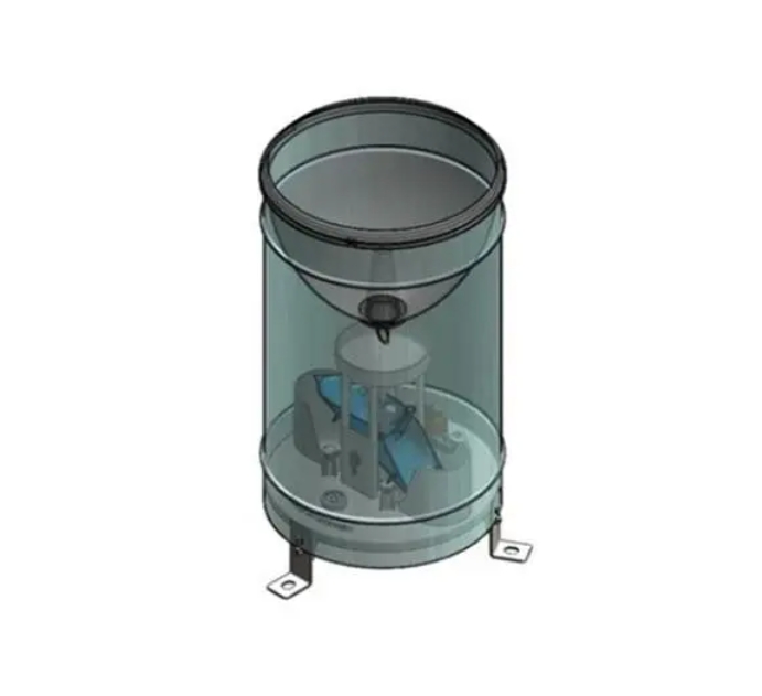
A tipping bucket rain gauge diagram shows how rainfall moves from the collector through the funnel to the tipping bucket mechanism and is finally converted into an electrical signal for a data logger, weather station or IoT monitoring system.
Understanding the internal structure is useful for product selection, installation, maintenance and troubleshooting. Most measurement problems can be traced to the rainfall collection path, bucket movement, leveling, signal detection or data conversion.
The NiuBoL NBL-W-RS tipping bucket rain gauge uses a calibrated mechanical tipping mechanism. In the standard 0.2 mm configuration, each completed tip represents 0.2 mm of rainfall.
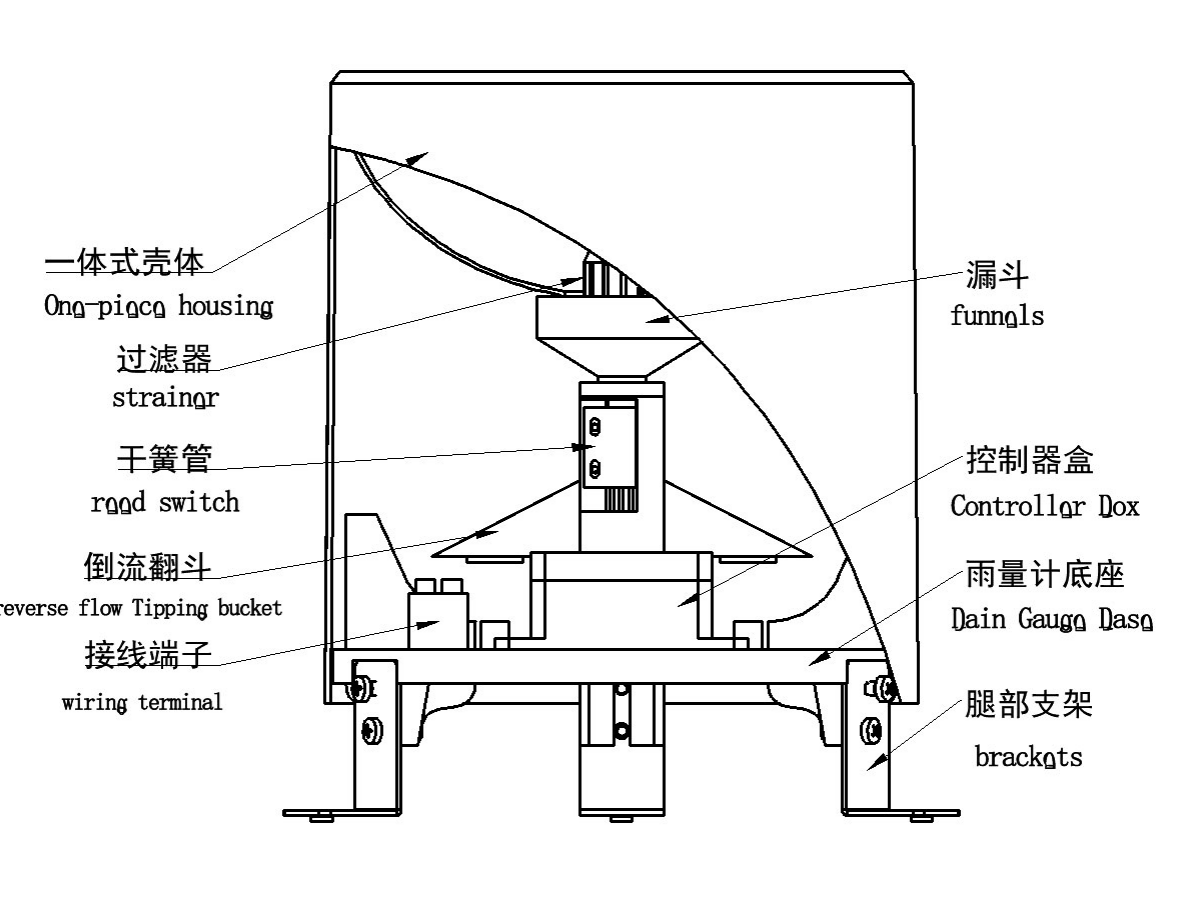
The diagram above shows the main internal components of a tipping bucket rain gauge. Rainwater enters through the upper collector and funnel, passes through the water path and reaches the tipping mechanism. When the calibrated amount of water is reached, the bucket changes position and triggers the sensing mechanism.
| Component | Function |
|---|---|
| Rain Collector | Collects precipitation over a defined opening area |
| Funnel | Directs collected rainwater toward the tipping mechanism |
| Strainer / Filter | Reduces entry of leaves and larger debris |
| Tipping Bucket | Tips when the calibrated water volume is reached |
| Reed Switch / Sensor | Detects each bucket movement and generates an electrical event |
| Signal Electronics | Converts or processes the signal depending on output configuration |
| Wiring Terminal | Connects the gauge to a logger, PLC, RTU or transmitter |
| Base and Mounting Brackets | Secure the rain gauge and allow correct leveling |
The rainfall measurement process can be understood as a simple flow path:
Rainfall → Collector → Funnel → Tipping Bucket → Sensor / Reed Switch → Electrical Signal → Data Logger
Rain falls into the collector opening. The collector area is precisely defined because rainfall is reported as an equivalent water depth rather than simply as the volume collected inside the instrument.
The funnel concentrates the collected water and directs it toward the tipping mechanism. Leaves, insects, dust or sediment in this section can restrict water flow and cause artificially low or delayed rainfall readings.
The tipping mechanism has two alternating collection sides. One side receives water while the other remains in the discharge position.
When the calibrated water volume is reached, the balance changes and the bucket tips. The filled side discharges while the opposite side moves into position to receive the next volume of rainwater.
The bucket movement activates a reed switch or another sensing element. The signal is then counted directly or processed by a transmitter depending on the output configuration.
For a 0.2 mm tipping bucket:
| Tips | Rainfall |
|---|---|
| 1 | 0.2 mm |
| 5 | 1.0 mm |
| 25 | 5.0 mm |
| 50 | 10.0 mm |
The timing between tipping events can also be used by the logger or software to calculate rainfall intensity.
For a Φ200 mm collector, the radius is 100 mm or 0.1 m.
Collector Area = π × 0.1² ≈ 0.031416 m²
A rainfall depth of 0.2 mm equals 0.0002 m.
0.031416 m² × 0.0002 m ≈ 0.000006283 m³
≈ 6.28 mL
Therefore, under ideal geometric conditions, approximately 6.28 mL entering a Φ200 mm collector corresponds to 0.2 mm of rainfall.
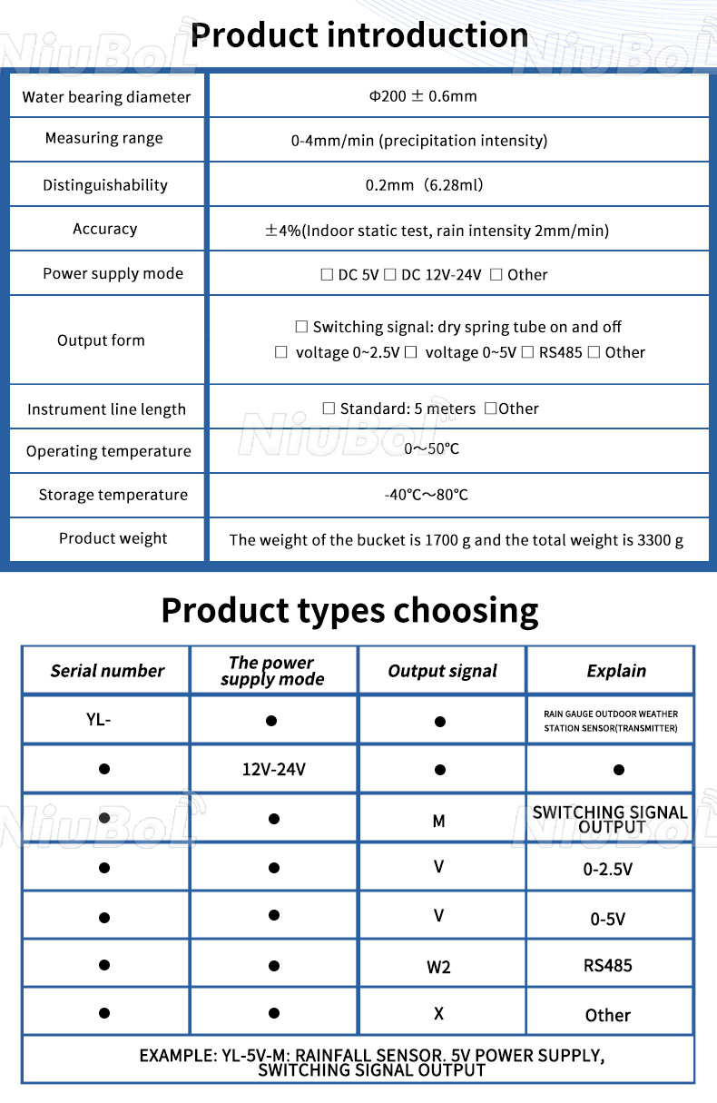
| Collector Diameter | Φ200 ±0.6 mm |
| Rainfall Intensity Range | 0–4 mm/min |
| Resolution | 0.2 mm |
| Equivalent Volume | Approx. 6.28 mL per 0.2 mm |
| Accuracy | ±4% under specified indoor static test conditions |
| Output Options | Switch / pulse, voltage or RS485 depending on configuration |
| RS485 Protocol | Modbus RTU |
| Standard Cable | 5 m |
The mechanical tipping action is the same, but the way the measurement reaches the control system depends on the selected output.
| Output Type | How It Works | Typical Receiver |
|---|---|---|
| Pulse / Switch | One switching event represents one calibrated tip | Pulse counter, weather logger or RTU |
| RS485 Modbus | Digital transmitter provides rainfall data through Modbus RTU | PLC, RTU, data logger or IoT gateway |
| Voltage | Transmitter converts rainfall measurement to an analog voltage signal | Analog acquisition system |
Rain → Tipping Bucket → Reed Switch → Pulse / Transmitter → Data Logger → 4G / Ethernet → Cloud or Private Server
It is useful to separate the mechanical measurement from the digital data processing. The tipping bucket creates the physical measurement event, while the logger or transmitter converts that event into the rainfall value displayed by the monitoring system.
A structural diagram is particularly useful when rainfall readings are abnormal because the problem can be traced through the measurement path.
| Symptom | Possible Cause | Check |
|---|---|---|
| No rainfall recorded | Blocked funnel | Inspect collector, filter and water path |
| Water enters but no signal | Bucket or switch problem | Check bucket movement and reed-switch response |
| Rainfall too low | Partial blockage or poor catch | Clean funnel and check installation exposure |
| Unstable readings | Gauge not level or unstable mounting | Check level and mounting base |
| Mechanical tips but logger shows zero | Wiring or input configuration | Check pulse input, wiring and logger settings |
| RS485 communication fails | Address, baud rate or A/B wiring issue | Verify Modbus settings and RS485 polarity |
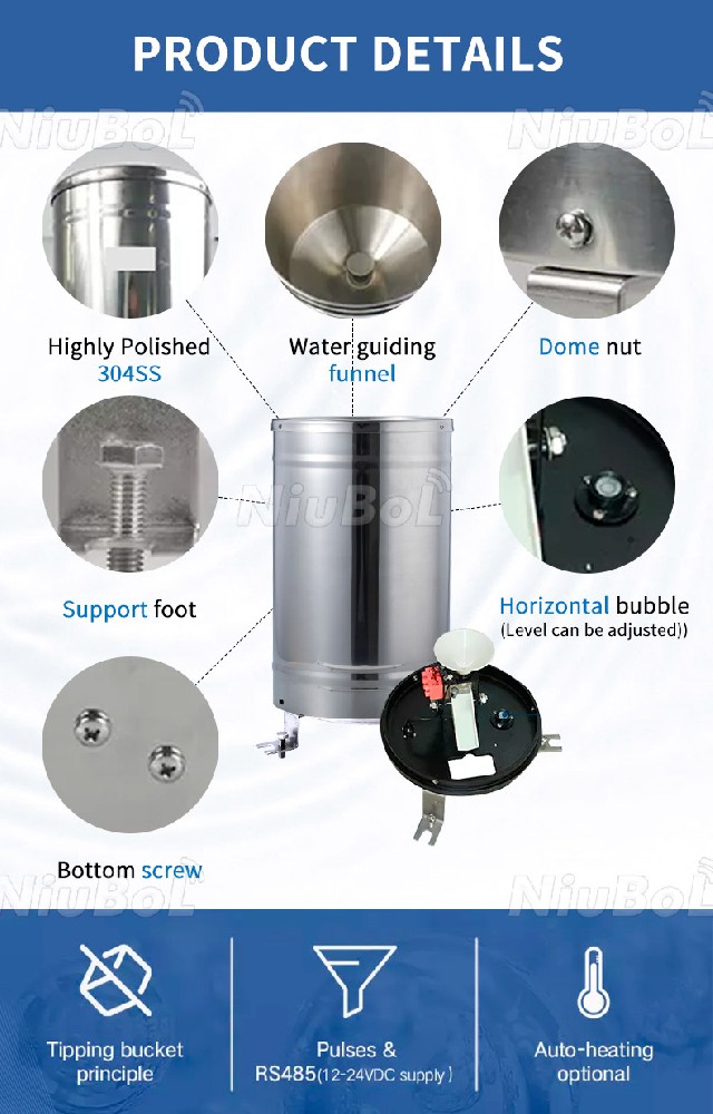
The tipping mechanism depends on mechanical balance. If the rain gauge is tilted, one side of the bucket may require a different effective amount of water before tipping.
During installation:
Place the gauge on a stable mounting surface.
Use the level indicator where provided.
Adjust the mounting feet until the instrument is level.
Recheck leveling after installation.
Check again if the mounting structure moves or settles.
Communication can remain completely normal even when the rainfall measurement is wrong.
For example, if leaves or insects partially block the funnel, the RS485 transmitter may still communicate correctly while insufficient water reaches the tipping bucket. This can result in rainfall readings that are lower than the actual precipitation.
Therefore, troubleshooting should check the physical rainfall path before assuming that every abnormal value is an electronic or communication fault.
The internal diagram explains how the instrument works, but installation conditions also affect rainfall catch.
Install the gauge in an open and representative location.
Avoid unnecessary obstruction from trees and buildings.
Avoid roof edges and surfaces that can create splash water.
Keep the gauge level.
Use a stable mounting base.
Keep the collector accessible for cleaning.
Protect cables from mechanical damage and standing water.
A1. The main parts include the collector, funnel, filter or strainer, tipping bucket mechanism, reed switch or sensor, wiring terminal, housing and mounting structure.
A2. One side collects a calibrated volume of water. When the balance point is reached, the mechanism tips and the opposite side moves into the collection position.
A3. It depends on the gauge design. For the standard NBL-W-RS 0.2 mm configuration, one completed tip represents 0.2 mm of rainfall.
A4. No. The mechanical bucket creates the measurement event. An electronic transmitter or data logger converts the detected event into a digital rainfall value for RS485 communication.
A5. A blocked funnel, restricted tipping bucket, poor leveling or installation obstruction can affect physical rainfall measurement even when the electronics and RS485 communication are functioning normally.
A6. The tipping mechanism relies on mechanical balance. Incorrect leveling can change how the two sides tip and affect measurement performance.
A7. Yes. Accumulated rainfall is calculated from the number of tips, while the timing between tips can be used to calculate rainfall intensity.
A8. A standard unheated tipping bucket is mainly intended for liquid precipitation. Snow or freezing precipitation requires a suitable heated or specialized instrument.
 NBL-W-ARS-Tipping-bucket-rain-gauge-instruction-manual.pdf
NBL-W-RS-Rain-sensors-instruction-manual-V4.0.pdf
NiuBoL provides tipping bucket rain gauges with pulse, voltage and RS485 configurations for weather stations, hydrology, agriculture, reservoirs and remote IoT rainfall-monitoring systems.
For product selection, provide the required resolution, output type, cable length, installation environment and whether the sensor will connect to a PLC, RTU, data logger or remote IoT gateway.
Related recommendations
Sensors & Weather Stations Catalog
 Agriculture Sensors and Weather Stations Catalog-NiuBoL.pdf
Weather Stations Catalog-NiuBoL.pdf
Agriculture Sensors Catalog-NiuBoL.pdf
Water Quality Sensor Catalog-NiuBoL.pdf
Related products
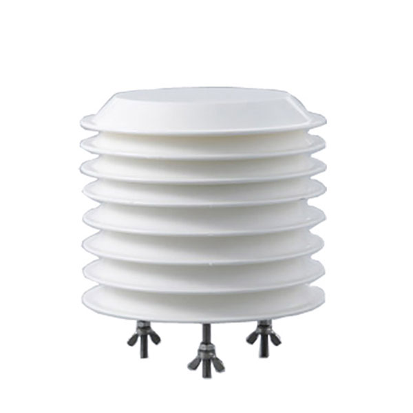 Combined air temperature and relative humidity sensor
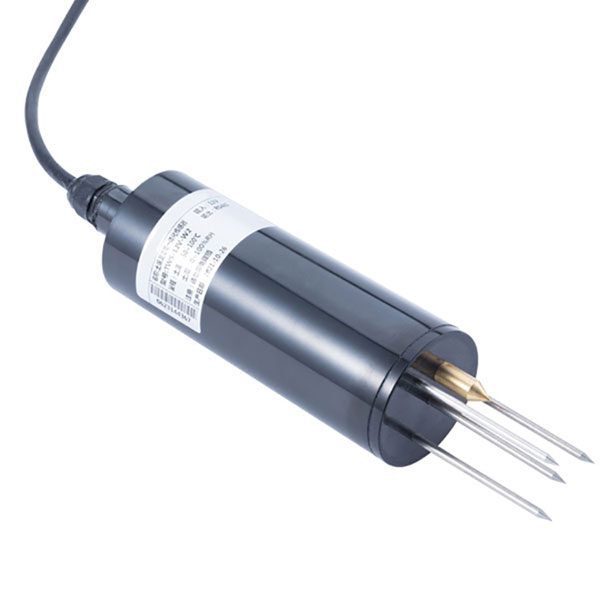 TDR Soil Moisture & Temperature Sensor for irrigation| RS485 |4-20mA| NBL-S-THR
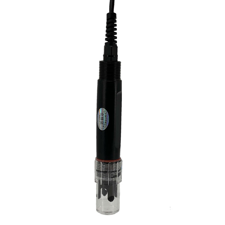 Soil pH sensor RS485 soil Testing instrument soil ph meter for agriculture |NBL-S-PH
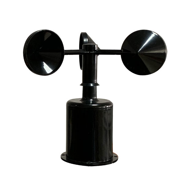 Wind Speed sensor Output Modbus/RS485/Analog/0-5V/4-20mA
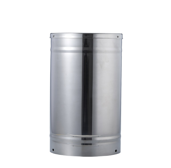 Tipping bucket rain gauge for weather monitoring auto rainfall sensor RS485/Outdoor/stainless steel
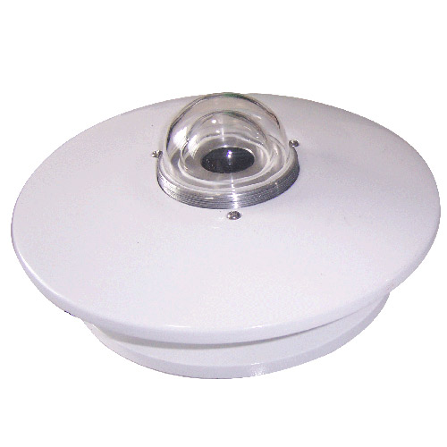 Pyranometer Solar Radiation Sensor 4-20mA/RS485

Screenshot, WhatsApp to identify the QR code
WhatsApp number:+8615367865107
(Click on WhatsApp to copy and add friends)