





— Blogs —
—Products—
 Consumer hotline +8618073152920
WhatsApp:+8615367865107
Address:Room 102, District D, Houhu Industrial Park, Yuelu District, Changsha City, Hunan Province, China
Product knowledge
Time:2026-09-08 08:00:00 Popularity:224
Choose the sensing principle by starting threshold, icing, contamination, directional response, service access and the intended safety or weather decision.
Project requirement for wind measurement system: In the system, field sensors feed a weather-station logger; the logger timestamps records and passes them to an RTU, gateway, local server or operating platform. Before releasing the wind-speed sensor integration purchase order, map the measuring point through cable protection, logger channel and network to the database tag and alarm destination. For wind speed sensor principle, a live number on a display is merely the first check. Across the end-to-end Wind Speed Sensor Principles data path, preserve engineering units, timestamps, Modbus addresses and device status.
| Decision field | Engineering requirement | Evidence for acceptance |
|---|---|---|
| Measurement purpose | State what action wind speed sensor principle should support | Approved monitoring objective |
| Location for wind speed sensor principle | Coordinates, depth or height, orientation and exposure | Drawing and installation photos |
| Data path for wind speed sensor principle | Sensor to logger, controller, gateway and platform | Live measurement with correct unit and timestamp |
| Maintenance for wind speed sensor principle | Safe access and responsible person | Inspection and service record |
| Parameter | Reference requirement | Why it matters |
|---|---|---|
| Measurement range for wind speed sensor principle | Model-dependent; state normal, peak and required resolution | Do not select by parameter name alone |
| Measurement accuracy for wind speed sensor principle | Use the approved model datasheet and define field acceptance separately | Catalogue accuracy is not the whole system uncertainty |
| Supply voltage for wind speed sensor principle | Confirm sensor, logger and remote power configuration | Check cable voltage drop and battery autonomy |
| Output signal for wind speed sensor principle | RS485 Modbus RTU is practical for digital sensors, while pulse or analog channels may still be required for selected rain, radiation or legacy instruments | Request wiring and protocol documents before panel work |
| Power consumption for wind speed sensor principle | Use maximum current for power budgeting, not only typical draw | Include modem and heater duty where applicable |
| Protection and temperature for wind speed sensor principle | Match enclosure, probe and connector ratings to the site | The lowest-rated exposed part controls field suitability |
| Cable and wetted material for wind speed sensor principle | Specify length, sheath, connector and exposed material by medium | Confirm chemical, UV and mechanical compatibility |
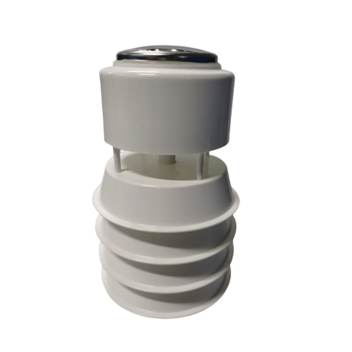
A practical technical specification, describe wind speed sensor principle as a measuring point with an operating purpose. NiuBoL can document the product-side interface and documentation after the buyer provides the site, expected range, cable distance and data destination.
Acceptance check for wind measurement system: The important limitation is that exposure, sensor height, orientation, mast vibration, lightning protection and nearby obstructions can matter more than a small difference in catalogue accuracy. If the instrument result later changes, those handover files let the owner distinguish a real field event from installation movement, fouling, configuration changes or communication loss.
| RFQ item | Information to provide | Cost or risk controlled |
|---|---|---|
| Application | Purpose and site for wind speed sensor principle | Prevents wrong product family |
| Measurement for wind speed sensor principle | Normal, alarm and peak range; required interval | Avoids under-range or needless overspecification |
| Integration for wind speed sensor principle | PLC/RTU/logger model, signal and protocol | Reduces panel rework |
| Mechanical for wind speed sensor principle | Mounting, depth or height, cable route and material exposure | Defines accessories and serviceability |
| Supply scope for wind speed sensor principle | Sensor only or complete station; documents and spares | Makes prices comparable |
| Commercial for wind speed sensor principle | Quantity, destination, delivery target and packing | Supports a realistic quotation |
Select wind speed sensor principle only when its measurement function, operating limits and interface match the documented project requirements.
Do not postpone the interface choice for Wind Speed Sensor Principles until after the control cabinet has been built. The wind speed sensor principle model, power demand and output must be frozen early enough for the integrator to allocate terminals, protection, addresses and data fields. If the host system has only analog inputs, document the exact 4-20 mA scaling on a suitable model. For an RS485 Modbus RTU version of Wind Speed Sensor Principles, obtain the register map before controller programming begins. A protocol name by itself doesn't prove plug-and-play compatibility.
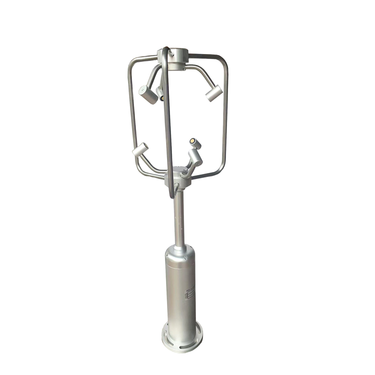
A1: Rotating cups convert wind force into shaft speed. It is widely used for horizontal wind speed and has an intuitive operating principle.
A2: propeller measures wind along its axis and is often paired with a vane. It can suit directional airflow where the sensor aligns with the wind.
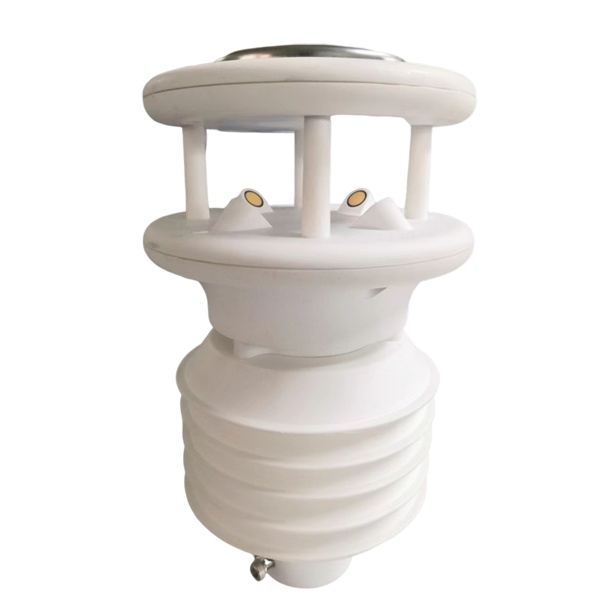
A3: It has no rotating parts and can measure wind speed and direction in one head. It still requires a clear acoustic path and correct orientation.
A4: Compare the stated starting threshold, resolution and response time of the exact models. Mechanical friction can affect low-speed response.
A5: Ice can stop moving parts and obstruct ultrasonic paths. Cold-climate projects may require heating, more power and a maintenance plan.
A6: Models with RS485, 4-20mA or voltage output can be integrated when the PLC supports the interface. Confirm scaling and direction convention.
A7: Check mast clearance, orientation, level where required, live response, units, direction convention and comparison with expected wind conditions.
A8: Mechanical sensors need bearing and rotor inspection; ultrasonic sensors need clean, undamaged transducers and acoustic paths. All types need secure alignment and cables.

Cup, propeller and ultrasonic wind sensors serve different applications. Choose by the required wind component, starting threshold, maintenance environment, response and mounting constraints rather than by appearance alone.
Prev:Tipping Bucket Rain Sensor: Principle and Installation
Next:Buoy Water Quality Monitoring System: What It Should Deliver
Related recommendations
Sensors & Weather Stations Catalog
 Agriculture Sensors and Weather Stations Catalog-NiuBoL.pdf
Weather Stations Catalog-NiuBoL.pdf
Agriculture Sensors Catalog-NiuBoL.pdf
Water Quality Sensor Catalog-NiuBoL.pdf
Related products
Combined air temperature and relative humidity sensor TDR Soil Moisture & Temperature Sensor for irrigation| RS485 |4-20mA| NBL-S-THR
 Soil pH sensor RS485 soil Testing instrument soil ph meter for agriculture |NBL-S-PH
 Wind Speed sensor Output Modbus/RS485/Analog/0-5V/4-20mA
 Tipping bucket rain gauge for weather monitoring auto rainfall sensor RS485/Outdoor/stainless steel
 Pyranometer Solar Radiation Sensor 4-20mA/RS485


Screenshot, WhatsApp to identify the QR code
WhatsApp number:+8615367865107
(Click on WhatsApp to copy and add friends)

